
AT E C ore
Configurations
RMX-10011 User Manual
ATE Core Configurations RMX-10011 User Manual
October 2017
377138A-01
Support
Worldwide Technical Support and Product Information
ni.com
Worldwide Offices
Visit
ni.com/niglobal to access the branch office web sites, which provide up-to-date
contact information, support phone numbers, email addresses, and current events.
National Instruments Corporate Headquarters
11500 North Mopac Expressway Austin, Texas 78759-3504 USA Tel: 512 683 0100
For further support information, refer to the NI Services appendix. To comment on National
Instruments documentation, refer to the National Instruments web site at ni.com/info and
enter the Info Code feedback.
© 2017 National Instruments. All rights reserved.

Legal Information
Limited Warranty
This document is provided ‘as is’ and is subject to being changed, without notice, in future editions. For the latest version,
refer to
ni.com/manuals. NI reviews this document carefully for technical accuracy; however, NI MAKES NO EXPRESS
OR IMPLIED WARRANTIES AS TO THE ACCURACY OF THE INFORMATION CONTAINED HEREIN AND
SHALL NOT BE LIABLE FOR ANY ERRORS.
NI warrants that its hardware products will be free of defects in materials and workmanship that cause the product to fail to
substantially conform to the applicable NI published specifications for one (1) year from the date of invoice.
For a period of ninety (90) days from the date of invoice, NI warrants that (i) its software products will perform substantially
in accordance with the applicable documentation provided with the software and (ii) the software media will be free from
defects in materials and workmanship.
If NI receives notice of a defect or non-conformance during the applicable warranty period, NI will, in its discretion: (i) repair
or replace the affected product, or (ii) refund the fees paid for the affected product. Repaired or replaced Hardware will be
warranted for the remainder of the original warranty period or ninety (90) days, whichever is longer. If NI elects to repair or
replace the product, NI may use new or refurbished parts or products that are equivalent to new in performance and reliability
and are at least functionally equivalent to the original part or product.
You must obtain an RMA number from NI before returning any product to NI. NI reserves the right to charge a fee for
examining and testing Hardware not covered by the Limited Warranty.
This Limited Warranty does not apply if the defect of the product resulted from improper or inadequate maintenance,
installation, repair, or calibration (performed by a party other than NI); unauthorized modification; improper environment;
use of an improper hardware or software key; improper use or operation outside of the specification for the product; improper
voltages; accident, abuse, or neglect; or a hazard such as lightning, flood, or other act of nature.
THE REMEDIES SET FORTH ABOVE ARE EXCLUSIVE AND THE CUSTOMER’S SOLE REMEDIES, AND SHALL
APPLY EVEN IF SUCH REMEDIES FAIL OF THEIR ESSENTIAL PURPOSE.
EXCEPT AS EXPRESSLY SET FORTH HEREIN, PRODUCTS ARE PROVIDED "AS IS" WITHOUT WARRANTY OF
ANY KIND AND NI DISCLAIMS ALL WARRANTIES, EXPRESSED OR IMPLIED, WITH RESPECT TO THE
PRODUCTS, INCLUDING ANY IMPLIED WARRANTIES OF MERCHANTABILITY, FITNESS FOR A
PARTICULAR PURPOSE, TITLE OR NON-INFRINGEMENT, AND ANY WARRANTIES THAT MAY ARISE FROM
USAGE OF TRADE OR COURSE OF DEALING. NI DOES NOT WARRANT, GUARANTEE, OR MAKE ANY
REPRESENTATIONS REGARDING THE USE OF OR THE RESULTS OF THE USE OF THE PRODUCTS IN TERMS
OF CORRECTNESS, ACCURACY, RELIABILITY, OR OTHERWISE. NI DOES NOT WARRANT THAT THE
OPERATION OF THE PRODUCTS WILL BE UNINTERRUPTED OR ERROR FREE.
In the event that you and NI have a separate signed written agreement with warranty terms covering the products, then the
warranty terms in the separate agreement shall control.
Copyright
Under the copyright laws, this publication may not be reproduced or transmitted in any form, electronic or mechanical,
including photocopying, recording, storing in an information retrieval system, or translating, in whole or in part, without the
prior written consent of National Instruments Corporation.
National Instruments respects the intellectual property of others, and we ask our users to do the same. NI software is protected
by copyright and other intellectual property laws. Where NI software may be used to reproduce software or other materials
belonging to others, you may use NI software only to reproduce materials that you may reproduce in accordance with the
terms of any applicable license or other legal restriction.
End-User License Agreements and Third-Party Legal Notices
You can find end-user license agreements (EULAs) and third-party legal notices in the following locations:
• Notices are located in the
<National Instruments>\_Legal Information and <National Instruments>
directories.
• EULAs are located in the
<National Instruments>\Shared\MDF\Legal\license directory.
•Review
<National Instruments>\_Legal Information.txt for information on including legal information in
installers built with NI products.
U.S. Government Restricted Rights
If you are an agency, department, or other entity of the United States Government (“Government”), the use, duplication,
reproduction, release, modification, disclosure or transfer of the technical data included in this manual is governed by the
Restricted Rights provisions under Federal Acquisition Regulation 52.227-14 for civilian agencies and Defense Federal
Acquisition Regulation Supplement Section 252.227-7014 and 252.227-7015 for military agencies.
Trademarks
Refer to the NI Trademarks and Logo Guidelines at ni.com/trademarks for more information on National Instruments
trademarks.
ARM, Keil, and µVision are trademarks or registered of ARM Ltd or its subsidiaries.
LEGO, the LEGO logo, WEDO, and MINDSTORMS are trademarks of the LEGO Group.
TETRIX by Pitsco is a trademark of Pitsco, Inc.
FIELDBUS FOUNDATION
™
and FOUNDATION
™
are trademarks of the Fieldbus Foundation.
EtherCAT
®
is a registered trademark of and licensed by Beckhoff Automation GmbH.
CANopen
®
is a registered Community Trademark of CAN in Automation e.V.
DeviceNet
™
and EtherNet/IP
™
are trademarks of ODVA.
Go!, SensorDAQ, and Vernier are registered trademarks of Vernier Software & Technology. Vernier Software & Technology
and
vernier.com are trademarks or trade dress.
Xilinx is the registered trademark of Xilinx, Inc.
Taptite and Trilobular are registered trademarks of Research Engineering & Manufacturing Inc.
FireWire
®
is the registered trademark of Apple Inc.
Linux
®
is the registered trademark of Linus Torvalds in the U.S. and other countries.
Handle Graphics
®
, MATLAB
®
, Real-Time Workshop
®
, Simulink
®
, Stateflow
®
, and xPC TargetBox
®
are registered
trademarks, and TargetBox
™
and Target Language Compiler
™
are trademarks of The MathWorks, Inc.
Tektronix
®
, Tek, and Tektronix, Enabling Technology are registered trademarks of Tektronix, Inc.
The Bluetooth
®
word mark is a registered trademark owned by the Bluetooth SIG, Inc.
The ExpressCard
™
word mark and logos are owned by PCMCIA and any use of such marks by National Instruments is under
license.
The mark LabWindows is used under a license from Microsoft Corporation. Windows is a registered trademark of Microsoft
Corporation in the United States and other countries.
Other product and company names mentioned herein are trademarks or trade names of their respective companies.
Members of the National Instruments Alliance Partner Program are business entities independent from National Instruments
and have no agency, partnership, or joint-venture relationship with National Instruments.
Patents
For patents covering National Instruments products/technology, refer to the appropriate location: Help»Patents in your
software, the
patents.txt file on your media, or the National Instruments Patent Notice at ni.com/patents.
Export Compliance Information
Refer to the Export Compliance Information at ni.com/legal/export-compliance for the National Instruments global
trade compliance policy and how to obtain relevant HTS codes, ECCNs, and other import/export data.
WARNING REGARDING USE OF NATIONAL INSTRUMENTS PRODUCTS
YOU ARE ULTIMATELY RESPONSIBLE FOR VERIFYING AND VALIDATING THE SUITABILITY AND
RELIABILITY OF THE PRODUCTS WHENEVER THE PRODUCTS ARE INCORPORATED IN YOUR SYSTEM OR
APPLICATION, INCLUDING THE APPROPRIATE DESIGN, PROCESS, AND SAFETY LEVEL OF SUCH SYSTEM
OR APPLICATION.
PRODUCTS ARE NOT DESIGNED, MANUFACTURED, OR TESTED FOR USE IN LIFE OR SAFETY CRITICAL
SYSTEMS, HAZARDOUS ENVIRONMENTS OR ANY OTHER ENVIRONMENTS REQUIRING FAIL-SAFE
PERFORMANCE, INCLUDING IN THE OPERATION OF NUCLEAR FACILITIES; AIRCRAFT NAVIGATION; AIR
TRAFFIC CONTROL SYSTEMS; LIFE SAVING OR LIFE SUSTAINING SYSTEMS OR SUCH OTHER MEDICAL
DEVICES; OR ANY OTHER APPLICATION IN WHICH THE FAILURE OF THE PRODUCT OR SERVICE COULD
LEAD TO DEATH, PERSONAL INJURY, SEVERE PROPERTY DAMAGE OR ENVIRONMENTAL HARM
(COLLECTIVELY, “HIGH-RISK USES”). FURTHER, PRUDENT STEPS MUST BE TAKEN TO PROTECT AGAINST
FAILURES, INCLUDING PROVIDING BACK-UP AND SHUT-DOWN MECHANISMS. NI EXPRESSLY DISCLAIMS
ANY EXPRESS OR IMPLIED WARRANTY OF FITNESS OF THE PRODUCTS OR SERVICES FOR HIGH-RISK
USES.

Compliance
Electromagnetic Compatibility Information
This hardware has been tested and found to comply with the applicable regulatory requirements and limits
for electromagnetic compatibility (EMC) as indicated in the hardware’s Declaration of Conformity (DoC)
1
.
These requirements and limits are designed to provide reasonable protection against harmful interference
when the hardware is operated in the intended electromagnetic environment. In special cases, for example
when either highly sensitive or noisy hardware is being used in close proximity, additional mitigation
measures may have to be employed to minimize the potential for electromagnetic interference.
While this hardware is compliant with the applicable regulatory EMC requirements, there is no guarantee
that interference will not occur in a particular installation. To minimize the potential for the hardware to
cause interference to radio and television reception or to experience unacceptable performance degradation,
install and use this hardware in strict accordance with the instructions in the hardware documentation and
the DoC
1
.
If this hardware does cause interference with licensed radio communications services or other nearby
electronics, which can be determined by turning the hardware off and on, you are encouraged to try to correct
the interference by one or more of the following measures:
• Reorient the antenna of the receiver (the device suffering interference).
• Relocate the transmitter (the device generating interference) with respect to the receiver.
• Plug the transmitter into a different outlet so that the transmitter and the receiver are on different branch
circuits.
Some hardware may require the use of a metal, shielded enclosure (windowless version) to meet the EMC
requirements for special EMC environments such as, for marine use or in heavy industrial areas. Refer to
the hardware’s user documentation and the DoC
1
for product installation requirements.
When the hardware is connected to a test object or to test leads, the system may become more sensitive to
disturbances or may cause interference in the local electromagnetic environment.
Operation of this hardware in a residential area is likely to cause harmful interference. Users are required to
correct the interference at their own expense or cease operation of the hardware.
Changes or modifications not expressly approved by National Instruments could void the user’s right to
operate the hardware under the local regulatory rules.
1
The Declaration of Conformity (DoC) contains important EMC compliance information and instructions
for the user or installer. To obtain the DoC for this product, visit
ni.com/certification, search by
model number or product line, and click the appropriate link in the Certification column.

© National Instruments | vii
Contents
Chapter 1
Introduction
Overview .......................................................................................................................... 1-1
Nomenclature.................................................................................................................... 1-1
Core System Layout ......................................................................................................... 1-2
Chapter 2
Installation and Configuration
Packaging Information ..................................................................................................... 2-1
Crate Dimensions ..................................................................................................... 2-2
Required Tools ......................................................................................................... 2-3
Hallway and Door Width Requirements .................................................................. 2-4
Uncrating the System................................................................................................ 2-4
Mechanical Stability and Loading.................................................................................... 2-5
Site Requirements............................................................................................................. 2-6
Power Connection..................................................................................................... 2-6
Power Recommendations ......................................................................................... 2-6
Cooling Requirements ...................................................................................................... 2-7
Exhaust ..................................................................................................................... 2-7
Chapter 3
Safety Information
Safety Requirements......................................................................................................... 3-1
AC Mains Cables...................................................................................................... 3-1
Removing Power ...................................................................................................... 3-2
Operator Safety Information............................................................................................. 3-3
Safety Features ......................................................................................................... 3-3
Safety Shutoff Thermostats .............................................................................. 3-3
Emergency Power Off (EPO) Panel ................................................................. 3-4
EPO Temperature Controller............................................................................ 3-4
Circuit Protection.............................................................................................. 3-4
Walls and Rear Door ........................................................................................ 3-4
Grounding......................................................................................................... 3-4
Chapter 4
System Bring Up
System Hardware.............................................................................................................. 4-1
Power Entry Panel (PEP).......................................................................................... 4-1
Main Disconnect and Circuit Breakers............................................................. 4-2
USB Ports ......................................................................................................... 4-3
Ethernet Port ..................................................................................................... 4-3
Contents
viii | ni.com
Connecting to a Network .................................................................................. 4-3
Removing Power............................................................................................... 4-3
Power Distribution Unit (PDU) ................................................................................4-3
Emergency Power Off (EPO) Panel ......................................................................... 4-4
Emergency Power Off (EPO) Button ...............................................................4-4
Main Power Switch........................................................................................... 4-4
Temperature Controller.....................................................................................4-4
Uninterruptable Power Supply (UPS).......................................................................4-4
System Block Diagrams.................................................................................................... 4-5
Power States...................................................................................................................... 4-6
Powering On .....................................................................................................................4-7
Chapter 5
Maintenance
Cleaning ............................................................................................................................5-1
Cleaning the Exterior ................................................................................................ 5-1
Cleaning Air Intake Filters .......................................................................................5-2
Replacement Parts............................................................................................................. 5-2
Calibration ........................................................................................................................5-3
Appendix A
Specifications
Appendix B
Internal Power Cables
Appendix C
NI Services
Glossary
Index
© National Instruments | 1-1
1
Introduction
This manual contains information on the core system elements including maintenance and
servicing information.
Documentation Icons
This icon denotes a suggestion, or recommendation to add clarity to the
documentation.
This icon denotes a caution, which advises you of precautions to take to avoid
injury, data loss, or a system crash.
Overview
The ATE Core Configurations contain the core mechanical, power, and safety infrastructure for
an automated test station. These systems provide the ultimate balance in standardized core
components to simplify design and documentation, along with the flexibility for NI and third
party instrumentation layout and are meant to be customized for a specific application.
Nomenclature
The ATE Core Configurations are uniquely identified by the voltage and power input type of the
system. Refer to Appendix A, Specifications for more details about ATE Core Configurations
power input ratings.
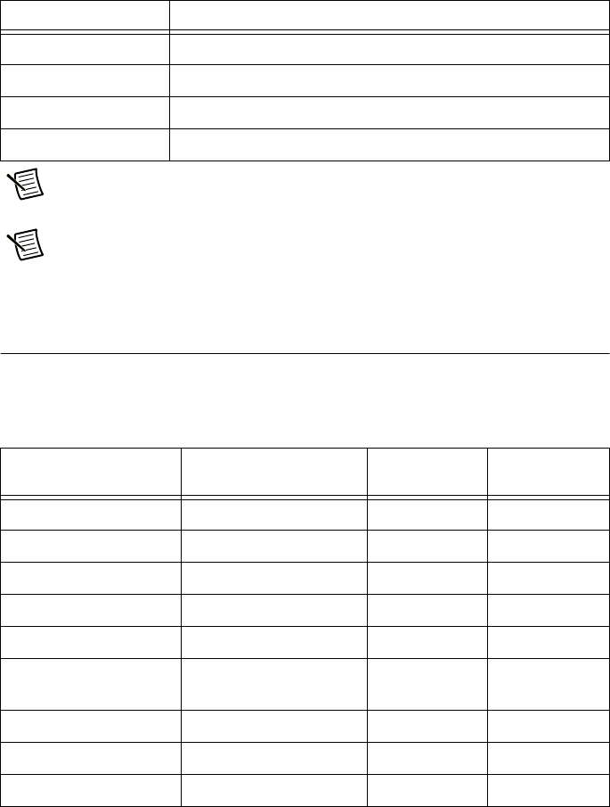
The following table identifies ATE Core Configurations system configurations. The model name
can be found on the system label located above the Power Entry Panel.
Table 1. ATE Core Configurations
System
Model Name
24 U Rack 40 U Rack
Low Power ATE-116H-A ATE-116F-A
Mid Power ATE-130H-A ATE-130F-A
High Power (Delta) ATE-3D16H-A ATE-3D16F-A
High Power (Wye) ATE-3W16H-A ATE-3W16F-A
1-2 | ni.com
Chapter 1 Introduction
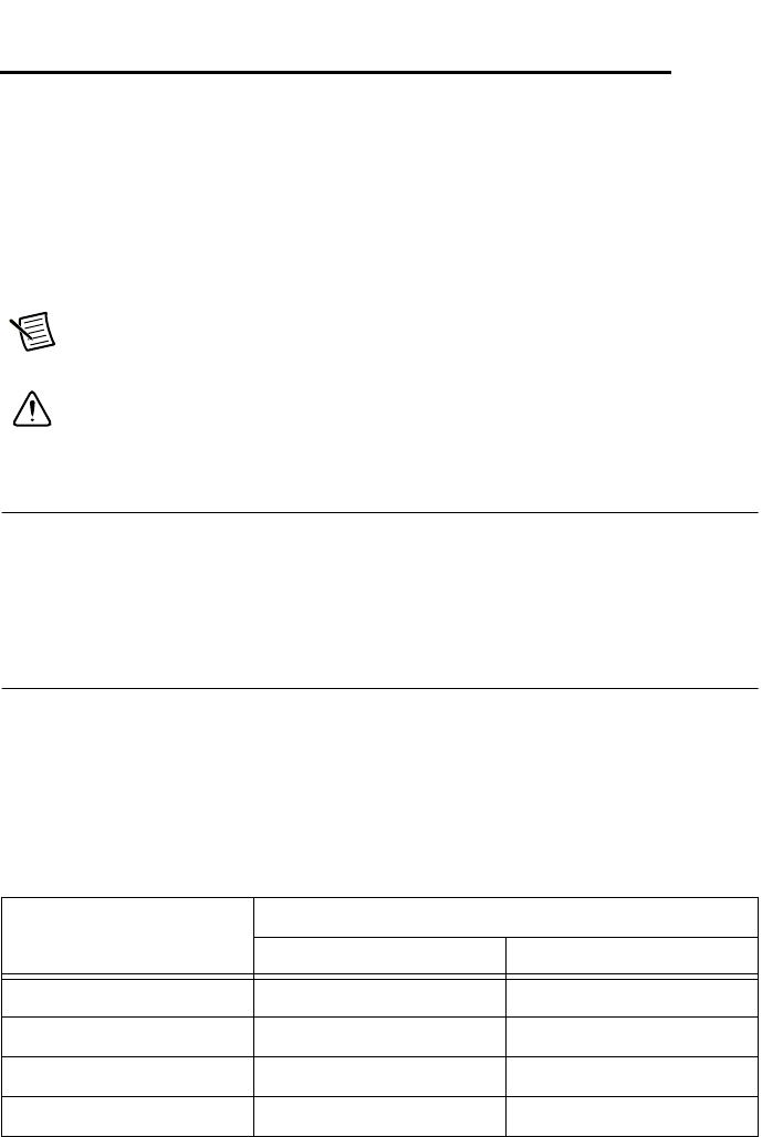
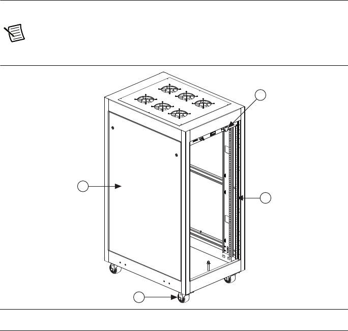
Core System Layout
The following figures show the locations of the ATE Core Configurations hardware.
Note The following figures show a 24 U Low Power configuration.
Figure 1-2. Front and Side View of ATE Core Configurations
1 Industrial Casters
2 Side Panel
3 Emergency Power Off (EPO) Panel
4 Mounting Rails
3
2
4
1
1-4 | ni.com
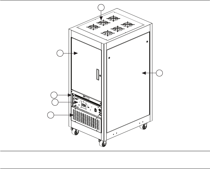
Chapter 1 Introduction
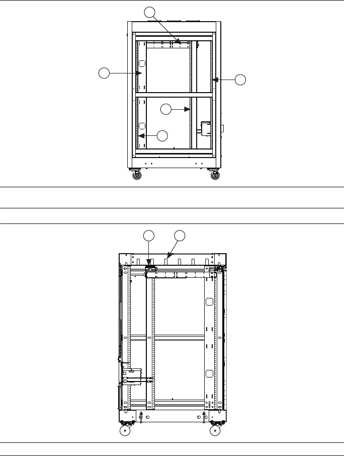
Figure 1-4. Side View of ATE Core Configurations
Figure 1-5. Cutaway View of Ethernet Switch Location
1 Cable Management
2 Power Distribution Unit
3 Mounting Rails
1 Ethernet Switch 2 Cable Management
1
2
3
3
3
1
2
© National Instruments | 2-1
2
Installation and Configuration
Packaging Information
ATE Core Configurations ship from the factory in a shipping crate. The shipping crate can
negotiate ramps and
small bumps such as door thresholds.
Carefully inspect the shipping crate and the rack for damage. Check for visible damage to the
metal work. If damage appears to have been caused during shipment, file a claim with the carrier.
Retain the packing material for possible inspection and/or reshipment.
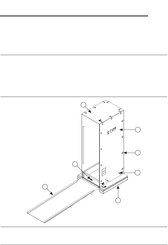
Figure 2-1. Rack Packaging Assembly
1Ramp Assembly
2 Removable Block
3 Top Panel
4 Side Panel (x2)
5 Clamp
6 Bolt Assembly (x8)
7 Base Assembly
1
2
3
4
5
6
7
2-2 | ni.com
Chapter 2 Installation and Configuration
Crate Dimensions
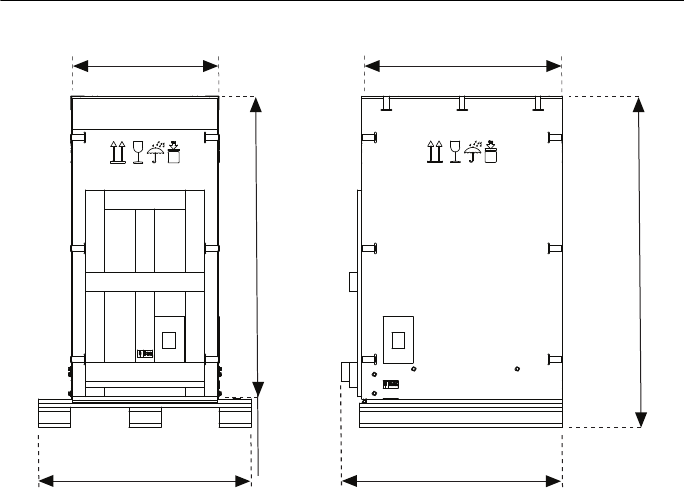
Figure 2-2. 24U Crate Dimensions
673 (26.5)
1545 (60.81)
1403 (55.25) [Ramp]
908 (35.75)
991 (39)
1031 (40.56)
Dimensions are in millimeters (inches)
© National Instruments | 2-3
ATE Core Configurations RMX-10011 User Manual
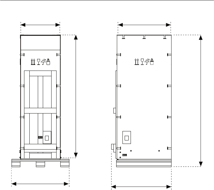
Figure 2-3. 40U Crate Dimensions
Required Tools
The ATE Core Configurations do not require special tools. Ensure that you have the following
standard tools to bring up, maintain, and troubleshoot.
• Screwdrivers
– Standard Head
• Large size for side panels and uncrating
• Small size for PDU DC connectors
– Phillips Head (#1 and #2)
– 1/2 in. wrench or socket (for uncrating)
991 (39)
1031 (40.56)
673 (26.5) 908 (35.75)
2115 (83.25) [Ramp]
2256 (88.81)
Dimensions are in millimeters (inches)
2-4 | ni.com
Chapter 2 Installation and Configuration
Hallway and Door Width Requirements
Verify that all doors, elevators, and passageways en route to the final location are large enough to
allow passage of the crated system. The crated system requires the use of a floor jack or forklift to
engage the pallet and lift the crated system. Consider this when evaluating hallways, doors, and
elevators along the route the system must travel.
If obstacles or lack of space restrict adequate crate movement, remove the system from the pallet
in
the receiving area and push it on the cabinet casters to the final destination.
The system is equipped with four rack mounted casters for easy movement throughout the facility.
Due to weight distribution of the instrumentation, the system is most stable during movement when
you push from the front or back of the rack. Avoid side-to-side movement except for final
positioning.
Caution Deploying the rack from the shipping crate requires moving it in a
back-to-front
direction. Never stand directly in front of the rack when loading or
unloading from a
shipping carton.
Uncrating the System
Note Do not discard any parts or packaging until you complete the system bring up
and verification process.
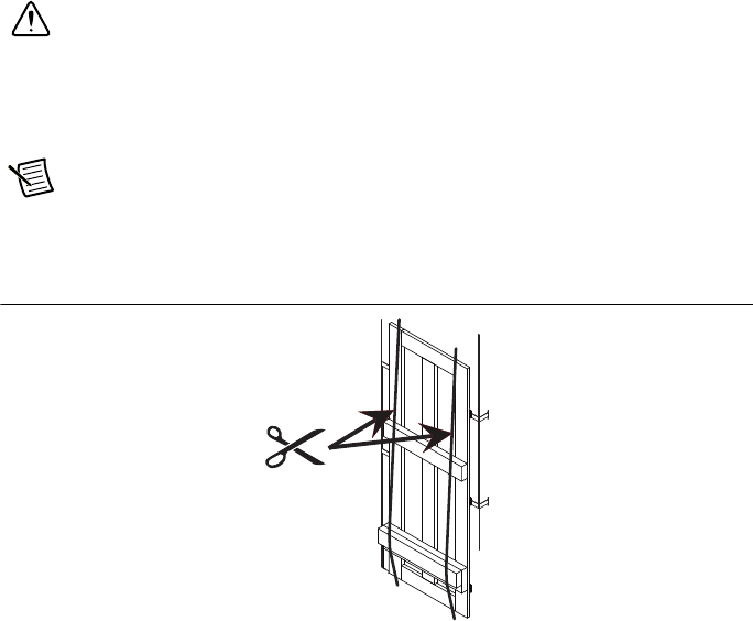
1. Carefully cut the two vertical straps affixed to the container.
Figure 2-4. Cutting Vertical Straps
2. Remove clamps securing the ramp.
3. Lower the ramp and ensure ramp is attached to the crate using metal track on the
base assembly.
4. Unscrew the four bolts on either side of the container (1/2 in. wrench or socket).

© National Instruments | 2-5
ATE Core Configurations RMX-10011 User Manual
5. Remove the removable block at the top of the ramp.
6. Roll the rack out of the crate using the ramp.
7. Remove VpCI bag.
8. Move the system to its designated area.
Mechanical Stability and Loading
Precautions were taken in designing your rack configuration to ensure physical stability of the
system. It is designed to not easily overbalance or tip. When adding equipment to the rack, it is
important to preserve stability.
• For IEC 61010-1 compliance, the rack and all its equipment must weigh less than 1,000 lb.
(453.5 kg), evenly distributed between each caster. Contact NI for more information about
the weight of your rack as received.
• There may be steel ballast plates at the bottom of the rack. Do not remove the steel ballast
plates. They are intended to improve the stability and safety of the rack based on its
specific configuration.
Caution Stability is based on the specific configuration of the system ordered,
when fully assembled. Your system may be shipped in separate crates or boxes.
Use caution to ensure stability while moving your system, and prior to assembly of
the configured system.
Caution If you remove equipment from the rack, it may no longer be compliant
with IEC 61010-1 stability standards. Ensure that any modifications you make to the
rack configuration maintain sufficient stability in accordance with IEC 61010-1.
Any modifications made to the system not specified by the manufacturer may reduce
the personal safety measures employed and compliance with IEC 61010-1.
Such modification, removal, or installation of equipment must be done by a qualified
and trained service person.
• To further improve the stability of the rack, it may be tethered to the floor or a wall. Make sure
to keep all cooling clearances open if the rack is to be tethered. Ensure your tether is sufficient
for the weight of the rack. Tethering should be done in accordance with local practices, and
any securement should be made between the system frame and the surrounding structure by
mechanical means able to support four times the load of the system.
• To ensure rack stability, any equipment over 10 lb. (4.5 kg) that hangs permanently outside
of the rack must have external support such as legs.

2-6 | ni.com
Chapter 2 Installation and Configuration
Site Requirements
This section describes the requirements for the location where the ATE Core Configurations is
operated. Verify
that you have met all requirements before powering on.
Power Connection
The ATE Core Configurations contains a Power Entry Panel for AC Mains and a
corresponding
power plug.
The system must meet the following power connection requirements:
• AC Mains power must be supplied to the system power plug.
• Power cord(s) must meet the following criteria:
– Cable/wires must be insulated for the highest voltage based on the input rating of the
system, and properly sized for current rating.
– Wire gauge specifications must meet or exceed requirements and in compliance with
all
applicable local codes and requirements.
– Wired by a qualified electrician.
Power Recommendations
National Instruments recommends the following requirements.
• Provide separate AC branch for the system due to the current requirements of the system.
• Copper wire for the system drop between the AC source and system.
• Before servicing the ATE Core Configurations, physically remove the Mains plug from the
power outlet.
• A minimum 20 A switch or circuit breaker must be provided in the installation for fully
disconnecting/removing power for the high power, 3-phase systems. This device must be
suitably located, easily reached, and identified as the disconnecting device for this system.
Caution You must press the Emergency Power Off (EPO) button, or turn the Main
Power Switch on the EPO to the off position, to fully disable the UPS output power
if the system includes the optional UPS.
Caution Verify the AC source and service conductor are sized correctly before
connecting the system.

© National Instruments | 2-7
ATE Core Configurations RMX-10011 User Manual
Cooling Requirements
The ATE Core Configurations ship with several features to help facilitate proper cooling, but due
to instrumentation layout, third party devices, cabling, and mass interconnect, it is important to
do a thorough thermal assessment of the final system assembly.
Each system ships with either a high or low speed fan panel including six 120 mm fans capable
of driving a total of 540 CFM in the low speed fan panel configuration, or 1350 CFM in the high
speed fan panel configuration. Additional airflow can be added with a 1U rack mount fan panel
that utilizes three 4 in. fans (270 CFM) for targeted areas within the rack.
Each system configuration also includes a 4U vent below the rear door to facilitate airflow into
the rack. Air filters are provided and it is recommended they be properly maintained based on
environmental conditions. These filters are user serviceable and replacement kits are available
on
ni.com.
Note Do not block the top (exhaust vent) or air intake.
NI recommends maintaining 2U of open space directly above and below the Power Entry Panel
to allow for proper airflow through the panel.
NI also recommends against adding equipment to the top 1U of the rack, or modifying the
position of the PDU and Ethernet switch located at the top of the rack. NI has validated sufficient
cooling with the PDU and Ethernet switch in their pre-installed locations.
Exhaust
The exhaust air from all instruments should have an unobstructed pathway to exit the rack.
Arrange instruments to provide a continuous airflow path from all instrument outlets.
© National Instruments | 3-1
3
Safety Information
Safety Requirements
The following general safety requirements and specifications must be observed during all phases
of operation of this equipment. Failure to comply with these precautions or with specific
warnings elsewhere in the system documentation violates safety standards of design,
manufacture, intended use, and could invalidate the warranty of the system. This equipment
contains voltage hazardous to human life and safety, and is capable of inflicting personal injury.
NI assumes no liability for the customer’s failure to comply with these requirements.
Note Using the ATE Core Configurations, or any component within, in a manner not
specified by the manufacturer may reduce or eliminate equipment and/or personnel
safety measures.
Caution Where this symbol is used, documentation must be consulted.
Before connecting the system to a power source, read this section and verify that you have
complied with all safety requirements and specifications.
Caution Before undertaking any bring up, troubleshooting, maintenance,
or exploratory procedure, carefully read the following caution notices.
Note Refer to the APC UPS Operation Manual for detailed information and
specifications for this accessory if applicable.
AC Mains Cables
The following cables are available from National Instruments under the following orderable
part numbers:
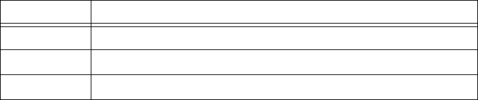
Table 3-1. Low Power Configuration Power Cables
Part Number Description
785708-01 AC, IEC C19 to NEMA 5-20P, 2.5 m
785714-04 AC, IEC C19 to CEE7, 3P, 16 A, 2.5 m
785714-09 AC, IEC C19 to CEE7, 3P, 16 A, 2.5 m (KCC)
785714-10 AC, IEC C19 to GB3, 3P, 16 A, 2.5 m
3-2 | ni.com
Chapter 3 Safety Information
-
Refer to Appendix B, Internal Power Cables for information about internal cables.
Removing Power
Caution To completely interrupt power to a single phase system, you must
disconnect the AC power cable. Do not position equipment so that it is difficult
to disconnect the cable.
To completely interrupt power to a three phase system, you must switch off the Main
Breaker on the Power Entry Panel. Do not position equipment so that it is difficult to
access the main breaker.
Caution You must press the Emergency Power Off (EPO) button, or turn the Main
Power Switch on the EPO to the off position, to fully disable the UPS output power
if the system
includes the optional UPS.
Table 3-2. Mid Power Configuration Power Cables
Part Number Description
785718-01 AC, Single Phase IEC 60309, 2P+E, Receptacle,
to IEC 60309, 2P+E, Plug, 2.5 m
785719-01 AC, Single Phase IEC 60309, 2P+E, Receptacle,
to NEMA L6-30, 2.5 m
785735-01 IEC 60309, 2P+E, pin and sleeve (connector only)
Table 3-3. High Power Configuration Power Cable
Part Number Description
785717-01 AC, Three Phase IEC 60309, 3P+N+E, Receptacle,
to IEC 60309, 3P+N+E, Plug, 2.5 m
785734-01 IEC 60309, 3P+N+E, pin and sleeve (connector only)

© National Instruments | 3-3
ATE Core Configurations RMX-10011 User Manual
Operator Safety Information
Cables and connectors are considered inaccessible if a tool (screwdriver, wrench, socket, etc.) or
a
key (equipment in a locked cabinet) is required to gain access to a conductive surface connected
to
any cable conductor.
Caution Access is prohibited to operators and is to be done by a trained service
person only.
Caution Filler panels shall be installed in all empty slots on the front of the rack so that
operator access to interior equipment surfaces is restricted.
Caution Verify equipment under test has adequate insulation between the cable
connections and any operator-accessible parts (doors, covers, panel shields, cases,
cabinets, etc.).
Safety Features
Safety Shutoff Thermostats
ATE Core Configurations has two safety shutoff thermostats (or four if the system is configured
with a UPS) on the interior surface of the fan cooling panel located at the top of the rack.
The thermostats are configured to shut the system off in the event the rack is unable to provide
adequate cooling, preventing a safety hazard to the user. When triggered by a severe over
temperature event, the thermostats will shut down the system by cutting power at the Power
Entry Panel AC outlet(s), immediately shutting off power to any downstream equipment
(including the PDUs).
Caution Once the thermostats have tripped, any touchable or accessible surface
should be allowed to cool to 65° C before servicing the system. All service must be
done by a trained service person.
To reset the thermostats once they have tripped, locate the thermostats on the interior surface of
the fan panel at the top of the rack, and depress the red button located on the bottom facing
surface of each thermostat. The system should now power on as normal once the powering on
procedure has been utilized. Refer to the Powering On section of Chapter 4, System Bring Up,
for more information about this procedure.
If the thermostats have tripped it is likely a result of a fault in the system (such as a fan failure)
and should be addressed before the system is allowed to resume normal operation.
Caution Do not attempt to reset the thermostats until their temperature is below 45° C.

3-4 | ni.com
Chapter 3 Safety Information
Note The thermostats are configured so they will not activate under normal
operating conditions, recommended power levels, cooling configuration, and
ambient environment. If the thermostats are triggered and no equipment fault can be
found in the system, the system may be configured in such a way that there is an
extreme thermal load in a small area of the system. Care should be taken to configure
the system so thermal loads are spread evenly throughout the interior of the system.
Caution Switch off the Main Breaker before attempting to reset the thermostats.
Emergency Power Off (EPO) Panel
The EPO Panel can be used to disable the PEP, PDU(s), optional UPS, and any equipment
connected to them.
EPO Temperature Controller
The secondary temperature controller on the EPO panel is user configurable and can be used to
control the operation of the system for thermal performance, but is not a safety temperature
protective device.
Circuit Protection
Several layers of circuit protection are designed into the systems. The Power Entry Panel has
circuit protection to ensure the overall system does not draw current beyond the Mains power
limit.
Walls and Rear Door
All configurations come with pre-installed removable side walls and locking rear door. Side
panels utilize quarter-turn inset screws for easy serviceability. The rear door may be easily
removed using the spring-loaded hinges attaching it to the rack frame.
Grounding
The Power Entry Panel must be connected to a power source that has a proper ground. You
should be able to choose any piece of equipment in the test system that is an end power consumer
and follow its path to ground back to the Power Entry Panel.

© National Instruments | 4-1
4
System Bring Up
Before powering on your system, ensure all equipment is present. Make sure all system
components are properly connected before proceeding. Your ATE Core Configurations system
will arrive from NI without interconnects between the modules and devices.
Note Your exact configuration may consist of all the required elements and any
optional components.
System Hardware
Power Entry Panel (PEP)
There are four distinct power configurations available with the ATE Core Configurations:
• Low Power
•Mid Power
• High Power (Delta)
• High Power (Wye)
Each Power Entry Panel contains:
• Applicable IEC power entry connector
– Low Power: IEC 60320 C20
– Mid Power: IEC 60309 2P+E
– High Power (Delta and Wye): IEC 60309 3P+N+E
• Applicable circuit protection
• Applicable line filter for EMI protection within the system
• Applicable kill-switch relay for emergency shutoff of Mains power via EPO Panel
• Two USB 3.0 ports with attached 2 m cable
• One Gigabit Ethernet port
• One external grounding lug with internal grounding plate connections for all rack mount
equipment
4-2 | ni.com
Chapter 4 System Bring Up
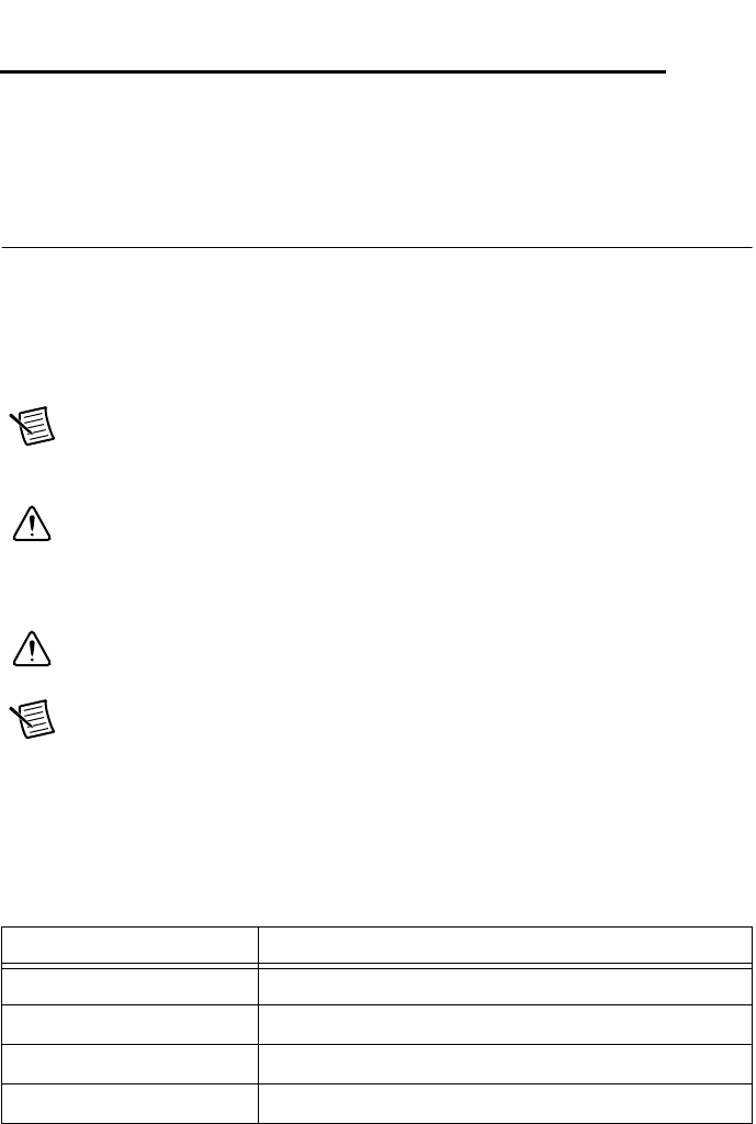
Figure 4-1. Front View of Power Entry Panel
Note Mid Power PEP shown, components are representative.
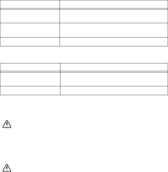
Figure 4-2. Rear View of Power Entry Panel Rear
Note Mid Power PEP shown, components are representative.
Main Disconnect and Circuit Breakers
The Main Breaker on the Power Entry Panel controls whether AC power will be allowed into
the rack. If the Main Breaker is off, the rack cannot be powered on.
The Mid Power, Power Entry Panel has two additional circuit breakers controlling power output
from the Power Entry Panel individually to each Power Distribution Unit in the system.
1 Power Inlet Connector
2 Main Breaker
3 Ethernet Port
4 USB Ports
5 Individual Outlet Breakers (Mid Power Only)
6 Ground Stud
1 DC Output to EPO Panel 2 Grounding Plate 3 Output Connector(s)
1
3
2
4
5
6
NATIONAL
INSTRUMENTS
1
2
3

© National Instruments | 4-3
ATE Core Configurations RMX-10011 User Manual
USB Ports
The Power Entry Panel has two USB ports which provide access to extension cables within the
rack. These cables can be connected to provide external access to USB ports on internal equipment.
Ethernet Port
The Power Entry Panel has an Ethernet port connected to a switch inside the rack to facilitate
network connectivity to internal equipment. Refer to Figure 1-5, Cutaway View of Ethernet
Switch Location for more details about the Ethernet Switch location.
Connecting to a Network
Complete the following steps to connect the ATE to a network.
1. Connect an active network cable to the Ethernet port on the Power Entry Panel
2. Configure the network and user settings according to the standard practices of your facility
and within the IP address setting restrictions.
Removing Power
Caution To completely interrupt power to a single phase system, you must
disconnect the AC power cable. Do not position equipment so that it is difficult
to disconnect the cable.
To completely interrupt power to a three phase system, you must switch off the main
breaker on the Power Entry Panel. Do not position equipment so that it is difficult to
access the main breaker. Do not proceed unless qualified personnel has reviewed all
installation instructions,
written warnings and cautions.
Caution You must press the Emergency Power Off (EPO) button, or turn the Main
Power Switch on the EPO to the off position, to fully disable the UPS output power
if the system
includes the optional UPS.
Power Distribution Unit (PDU)
A PDU takes an input power signal and distributes it to a number of outlets that can power
components of the system. These internal power outlets from the PDU have a rated voltage
and current and are available for both alternating and direct current.
• Low Power ATE Core Configuration systems utilize a single-phase PDU that supports
global voltages (100-240 V, 50-60 Hz) and has a 20 A (IEC C19) input connector which
cables directly to the Power Entry Panel.
• Mid Power ATE Core Configuration systems support double the total system power of the
low-power systems. Mid Power systems utilize two of the single-phase PDUs with the
exception that the second PDU does not provide DC outputs. Both PDUs wire directly
to the Power Entry Panel.
4-4 | ni.com
Chapter 4 System Bring Up
• High Power ATE Core Configuration systems utilize a three-phase PDU that supports
global voltages (200-208 V Delta and 380-415 V Wye, 50-60 Hz) and has a fixed 16 A
(IEC 60309 3P + N + E) power cable which connects directly to the Power Entry Panel.
Refer to your Power Distribution Unit user documentation for more information about the PDU.
Emergency Power Off (EPO) Panel
When a test system encounters a serious issue or an emergency is taking place in the facility,
operators need the ability to quickly and cleanly power off the test system. EPO mechanisms are
included on the ATE Core Configurations to simplify connectivity and inhibit power switching.
Operators may use the EPO to reset a system in an error state, prevent damage to a DUT, or even
prevent harm to themselves.
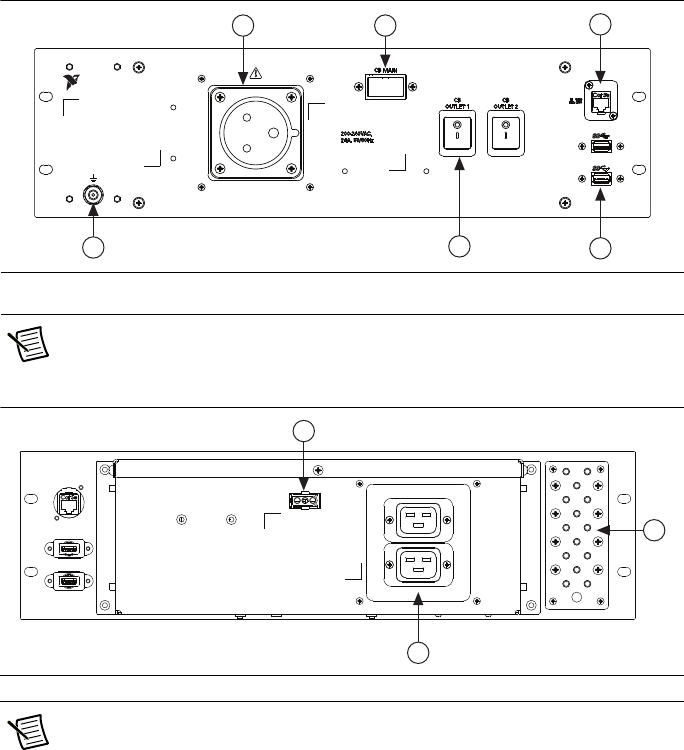
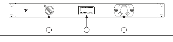
Figure 4-3. EPO Panel
Emergency Power Off (EPO) Button
The EPO button is one way to control whether the system is powered. If the EPO button is
pressed, power will not flow past the PEP or optional UPS. To release the EPO button once
it has been pressed, rotate it clockwise.
Main Power Switch
The Main Power Switch is the primary way of controlling whether the system is active. It toggles
between two positions: Standby and On.
Temperature Controller
The Temperature Controller (AutomationDirect SL4824-RR-D) will shut off the rack if the
internal temperature reaches a certain user programmable level. The controller measures
temperature based on the location of the attached thermocouple.
Uninterruptable Power Supply (UPS)
You can use the UPS to power critical components in your system during power loss, brownouts,
and during normal operation as well. The UPS delivers power with a dependable voltage and
current supply. It acts as a battery power supply after a power outage or significant brownout.
Refer to your Uninterruptable Power Supply user documentation for more information about the UPS.
1 Main Power Switch 2 Temperature Controller 3 EPO Button
1 2 3
NATIONAL
INSTRUMENTS
© National Instruments | 4-5
ATE Core Configurations RMX-10011 User Manual
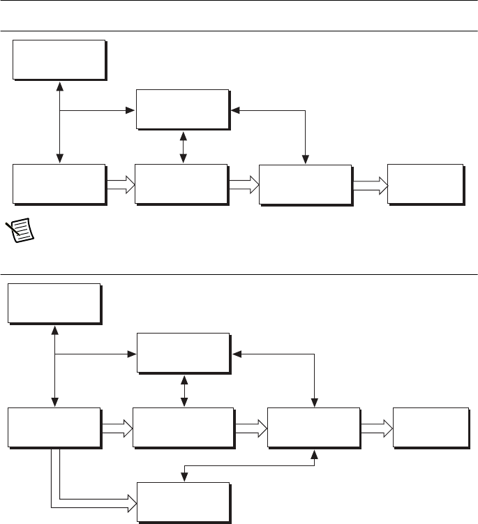
System Block Diagrams
Figure 4-4. Low Power System Block Diagram
Note PDU connects directly to the PEP if there is not a UPS installed.
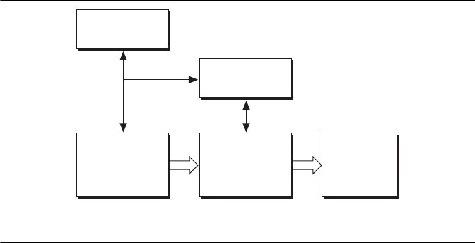
Figure 4-5. Mid Power System Block Diagram
Safety Shutoff
Thermostats
Power Entry Panel
(PEP)
Emergency Power
Off (EPO)
Panel
Rack Fans
Power Distribution
Unit (PDU)
Uninterruptable
Power Supply (UPS)
[Optional]
Emergency Power
Off (EPO)
P
anel
Safety Shutoff
Thermostats
Power Distribution
Unit (PDU)
Uninterruptable
Power Supply (UPS)
[Optional]
Power Entry Panel
(PEP)
Power Distribution
Unit (PDU)
Rack Fans
4-6 | ni.com
Chapter 4 System Bring Up
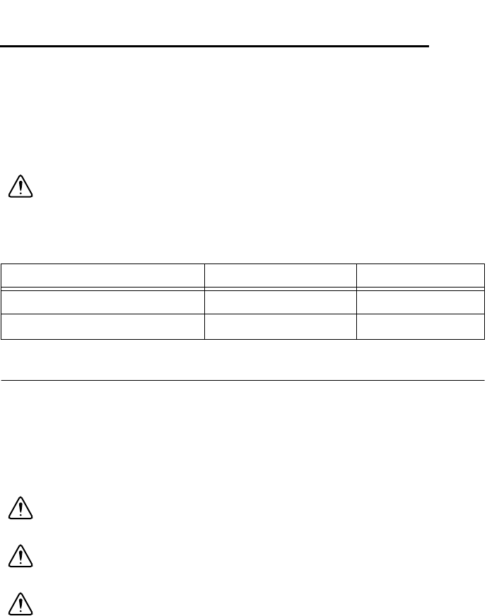
Figure 4-6. High Power System Block Diagram
Power States
The ATE Core Configuration system has multiple states of operation:
• Off—The system is entirely disabled with no power passing through the line filter or any
internal test system components.
To turn power off, switch the Main Beaker on the Power Entry Panel to the off position, or
disconnect Mains power from the Power Entry Panel.
• Standby—DC power is passing out of the PEP and into the thermostat EPO panel in the
Standby state.
The system is in Standby MAINs power is connected to the PEP and Main Breaker on the
PEP is in the on position, but one (or more) of the following is true:
– EPO button is depressed
–Main Power Switch on EPO Panel is off
– Temperature controller on the EPO Panel is reading a higher temperature than the
programmed shutoff value
– Safety shutoff thermostats have detected an unsafe air exit temperature
• On—A change to this state begins the main power on sequence of the test system. All
PDUs receive AC power and enable outlets to other system equipment.
• Emergency Power Off (EPO)—The EPO immediately cuts AC power from the PEP,
PDU(s), and optional UPS when a user or system monitor recognizes an unacceptable
operating condition. This returns the system to the Standby state until the EPO button is
released. The system will power back up once the EPO button is released, unless the Main
Power switch or Main Breaker are turned off.
Safety Shutoff
Thermostats
3 Phase
Power Entry Panel
(PEP)
Emergency Power
Off (EPO)
Panel
3 Phase
Power Distribution
Unit (PDU)
Single Phase
Outputs
Rack Fans

© National Instruments | 4-7
ATE Core Configurations RMX-10011 User Manual
Powering On
Complete the following steps to power on the ATE Core Configurations.
Caution Do not proceed unless qualified personnel has reviewed all installation
instructions,
written warnings, and cautions.
1. Verify that the Power Inlet Connector on the Power Entry Panel is connected to AC Mains.
2. Verify that the Main Breaker (and individual outlet breakers on Mid Power Panel) on the
back of the Power Entry Panel is in the ON position.
3. Confirm that the Emergency Power Off (EPO) button is not depressed.
4. Verify that the programmed temperature shutoff value of the temperature controller located
on the EPO Panel is above the current temperature reading in the system.
5. Rotate the Main Power switch, located on the EPO panel, to the On position.
© National Instruments | 5-1
5
Maintenance
This section describes preventative maintenance procedures, how often the
procedures need to be
performed, and where further maintenance details can be found.
Caution Always disconnect the AC power cable, and switch the Main Breaker to the
off position, before cleaning or servicing the system.
Cleaning
Cleaning the Exterior
Clean exterior surfaces with a dry lint-free cloth or a soft-bristle brush. If any dirt remains, wipe
with a cloth moistened in a mild soap solution. Remove any soap residue by wiping with a cloth
moistened with clear water. Do not use abrasive compounds on any part of the ATE Core
Configurations.
Caution Avoid getting moisture inside the system during exterior cleaning.
Use only enough
moisture to dampen the cloth.
Caution Do not wash the front- or rear-panel connectors or switches. Cover these
components
while cleaning the ATE Core Configurations.
Caution Do not use harsh chemical cleaning agents; they may damage the system.
Av o i d
chemicals that contain benzene, toluene, xylene, acetone, or similar solvents.
Table 5-1. Required Maintenance Schedule
Procedure Frequency Required
Cleaning exterior As needed Yes
Cleaning air intake
filter(s) Monthly, as needed Yes
5-2 | ni.com
Chapter 5 Maintenance
Cleaning Air Intake Filters
Clean the air intake filters using warm water with a mild soap solution, then air dry the filters to
remove moisture.
Caution Avoid installing wet filters into the ATE Core Configurations. Verify that
the filters are
thoroughly dry before re-installing.
Replacement Parts
Optional replacement power entry panels are available from National Instruments. The following
table lists available power entry panels and their orderable part numbers.
Table 5-2. Replacement Power Entry Panels
Part Number Model Description
785797-01 PEP-116 RMX-10040 Power Entry Panel (1-Phase, 16 A)
785798-01 PEP-130 RMX-10040 Power Entry Panel (1-Phase, 24 A)
785799-01 PEP-3W16 RMX-10040 Power Entry Panel (3-Phase Wye, 16 A)
785800-01 PEP-3D16 RMX-10040 Power Entry Panel (3-Phase Delta, 16 A)
Table 5-3. Spare and Replacement Parts
Part Number Description
784839-01 Spare caster set
785520-01 Spare air filter panel
785791-01 Replacement air filters, Qty 5
784840-01 Spare fan panel (low speed)
784840-02 Spare fan panel (high speed)
785515-01 Spare side panel 24U
785516-01 Spare side panel 40U
785517-01 Spare rear door panel 24U
785518-01 Spare rear door panel 40U
785521-01 Spare mounting rails 24U, Qty 2
785522-01 Spare mounting rails 40U, Qty 2
© National Instruments | 5-3
ATE Core Configurations RMX-10011 User Manual
Note Other replacement parts available. Contact NI for more information.
Note Not all default components inside the ATE Core Configurations are eligible
for service program coverage. The items eligible for service program coverage
include the PDU, EPO Panel, and the Moxa Ethernet Switch.
Calibration
Calibration for each ATE Core Configurations component is available and can be coordinated
through
your local sales representative, or by contacting the designated support
resources.
785523-01 Spare cable manager 24U
785524-01 Spare cable manager 40U
785512-01 1U filler panels for 19 in. rack. Qty 5.
785513-01 3U filler panels for 19 in. rack. Qty 3.
Table 5-4. Component Repair and Calibration for ATE Core Configurations
Component Required/Optional Serviceable
Calibration
Required
Rack Required No No
Rack Panels Optional No No
Rack Fan Panel Required No No
Air Filter Required No No
UPS Optional No No
Rack Mount for UPS Required
(when UPS is mounted)
No No
Power Input Connectors Required No No
PDU Required Yes No
Ethernet Switch Required Yes No
Table 5-3. Spare and Replacement Parts (Continued)
Part Number Description

© National Instruments | A-1
A
Specifications
This section contains specifications for the ATE Core Configurations.
Mechanical
Contact National Instruments for the weight of your rack as configured. To estimate your rack’s
weight without a scale, add the weight of each piece of equipment in the rack to the following base
values:
Base configuration weight
(rack, fan panel, power entry panel, PDU)....... 320 lb. (145 kg)
Ballast plate weight (each) ............................... 45 lb. (20.4 kg)
Maximum weight (Base configuration, and all equipment installed, stored, or attached to rack)
24U, 40U rack........................................... 1,000 lb. (453.5 kg), evenly distributed across
each caster
Keyboard shelf (optional)................. 30 lb. (13.6 kg)
Storage drawer (optional) ................. 30 lb. (13.6 kg)
The outlet circuit breaker(s) on the power entry panels PEP-116 and PEP-130 for Low and
Mid power ATE Core Configurations are rated for an impact energy level of IK06 (1J),
when tested with a direct vertical impact per IEC 61010-1, 3rd Ed., Table 15 and Clause 8.2.
The circuit breakers should be guarded against impacts exceeding 1J.
Core System Hardware
24U Rack Dimensions
System height ................................................... 53.5 in. (1,358.9 mm)
System width .................................................... 23 in. (584.2 mm)
System depth..................................................... 31.5 in. (800 mm)
Mountable depth ............................................... 29.5 in. (749.3 mm)
Max static load.................................................. 1,000 lb. (453.5 kg), evenly distributed across
each caster
A-2 | ni.com
Appendix A Specifications
40U Rack Dimensions
System height....................................................81.5 in (2,070.1 mm)
System width.....................................................23 in. (584.2 mm)
System depth.....................................................31.5 in. (800 mm)
Mountable depth ...............................................29.5 in. (749.3 mm)
Max static load..................................................1,000 lb. (453.5 kg), evenly distributed across
each caster
Environment
Maximum altitude.............................................2,000 m (800 mbar)
Allowable power dissipation is decreased by
25% at 2000 m. Refer to Tables A-1 through
A-5 in the Maximum Thermal Load section for
more information.
Pollution degree ................................................2
Indoor use only.
Overvoltage category ........................................II
Operating Environment
Ambient temperature is defined as the temperature that exists just outside of the air intake on
the bottom rear of the rack. This temperature may be higher than ambient room temperature
depending on
the surrounding equipment and/or blockages present. You must ensure that this
ambient
temperature does not exceed the rated ambient temperature range.
Ambient temperature range...............................5° C to 40° C
Relative humidity range ....................................10% to 80%, non condensing;
For proper ventilation, keep the following areas clear of obstructions:
Above top of fan panel......................................30 in. (762 mm)
Adjacent to the intake panel..............................12 in. (304.8 mm)
Storage Environment
Ambient temperature range ..............................0 °C to 65 °C
Relative humidity range....................................10% to 80%, non condensing

© National Instruments | A-3
ATE Core Configurations RMX-10011 User Manual
Acoustic Emissions
Sound Pressure Level (at Operator Position)
High speed fan panel ........................................ 92 dBA max. at operator position
85 dBA max. at bystander position (1 m away)
Caution All personnel must use hearing protection while the RMX-10011 system
with a high speed fan panel is in operation.
Electrical
AC Ratings
Low Power (ATE-116H-A, ATE-116F-A)
Rating
Input ............................................................... 100 to 240 VAC, 16 A, 50/60 Hz (No UPS)
100 to 120 VAC, 16 A, 50/60 Hz (with 120 V UPS)
200 to 240 VAC, 16 A, 50/60 Hz (with 240 V UPS)
PDU Output .............................................. 100 to 120 VAC, 10 A (per receptacle), 50/60 Hz
Total AC Output ............................... 15.2 A with low speed fan panel
12.9 A with high speed fan panel
8.7 A with DC supply fully loaded
PDU Output .............................................. 200 to 240 VAC, 10 A (per receptacle), 50/60 Hz
Total AC Output ............................... 15.5 A with low speed fan panel
14.5 A with high speed fan panel
12.4 A with DC supply fully loaded
Mid Power (ATE-130H-A, ATE-130F-A)
Rating
Input.......................................................... 200 to 240 VAC, 24 A, 50/60 Hz
PDU Output (each) ................................... 200 to 240 VAC, 16 A total,
10 A maximum per receptacle, 50/60 Hz
Total AC Output of PDU with DC.....15.5 A with low speed fan panel
14.5 A with high speed fan panel
12.4 A with DC supply fully loaded
PDU Output (combined)........................... 200 to 240 VAC, 24 A maximum, 50/60 Hz
Note 24 A maximum must account for power consumed by fan panel and other
required DC loads.
A-4 | ni.com
Appendix A Specifications
High Power 3-Phase Wye (ATE-3W16H-A, ATE-3W16F-A)
Rating
Input................................................................220/380 to 240/415 VAC, 16 A, 50/60 Hz,
3P+N+PE, 3
PDU Output (each phase) .........................220 to 240 VAC,
10 A maximum per C13 receptacle,
16 A maximum per C19 receptacle,
50/60 Hz (single phase)
Bank J1 .............................................15.5 A with low speed fan panel
14.4 A with high speed fan panel
12.7 A with DC supply fully loaded
High Power 3-Phase Delta (ATE-3D16H-A, ATE-3D16F-A)
Rating
Input ..........................................................200 to 208 VAC, 16 A, 50/60 Hz, 3P+PE, 3
PDU Output (each phase) .........................200 to 208 VAC, 9.2 A, 50/60 Hz (single phase)
Bank J1 .............................................8.7 A with low speed fan panel
7.7 A with high speed fan panel
5.6 A with DC supply fully loaded
Note Loads connected to the PDU Output receptacles/banks must be within the
maximum ratings of the PDU and should be balanced between the outputs to ensure
optimal performance.
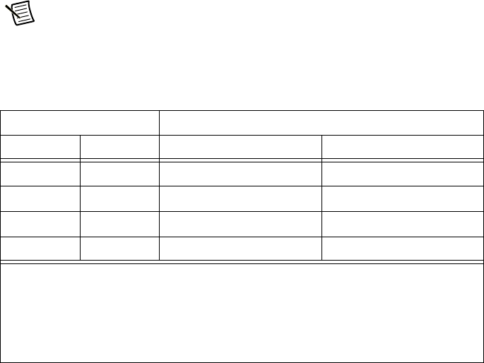
DC Ratings
Maximum Output Current
Output Voltage 100 to 120 VAC Input 200 to 240 VAC Input
DC1 12 VDC 10.4 A 12.5 A
DC2 24 VDC 5.2 A 6.25 A
DC3 24 VDC 5.2 A 6.25 A
DC4 48 VDC 2.6 A 3.13 A
• The low speed fan panel consumes 1.38 A at 24 VDC (DC2).
• The high speed fan panel consumes 5.1 A each from both 24 VDC outputs (DC2 and DC3).
For a total of 10.2 A.
• Ethernet hub consumes 0.1 A at 48 VDC (DC4)
• Available output current must be reduced by current drawn by fan panel and Ethernet hub.

© National Instruments | A-5
ATE Core Configurations RMX-10011 User Manual
Maximum Thermal Load
The following tables represent the maximum power that can be dissipated inside the rack for a
given ambient environment, fan panel selection, and lowest thermally rated equipment installed
in the rack. Additional power beyond the rated levels can be passed through to equipment
located externally to the rack (for example, using NI 1U RMX DC Power Supplies to power a
device under test where the load is physically outside of the rack).
Caution The ATE Core Configurations have been validated and rated to work with
certified equipment with ambient temperature ratings that fall within the maximum
internal temperature ratings of 45 °C or 50 °C in the following tables.
Equipment with ambient temperature ratings below 45 °C have not been validated to
work with the ATE Core Configurations systems. If equipment rated below 45 °C is
used, care must be taken to ensure the operating conditions of the equipment are not
violated. Consideration should be given to the thermal load around the equipment, the
location of the equipment’s air intake, exhaust air location of nearby equipment, and
the end use ambient environment the system will be installed in.
Please refer to following examples for guidelines on using the tables.
Example 1 A mid power rack will be used in a typical manufacturing
environment (28 °C ambient) with a low speed fan panel, and the
rack configuration will include equipment that has operational
ambient temperature ratings up to 45 °C. The maximum power
that can be dissipated in this rack is 2,550 W.
Example 2 A high power Wye three phase rack will be used in a typical room
temp environment (23 °C ambient) with a high speed fan panel,
and the rack configuration will contain equipment that has
operational ambient temperature ratings of 50 °C (and no
equipment with a maximum rating below 50 °C). The maximum
power that can be dissipated in this rack is 8,500 W.
Note The ambient temperature ratings and power dissipation limitations in the chart
above do not guarantee the thermal performance of equipment in the rack, only that the
rack contains adequate cooling capacity to provide the rated internal rack ambient
needed to support properly rated and installed equipment. Ensure that individual pieces
of equipment installed in the rack are within their specified operational ranges.
Note All equipment inside the rack must be powered, directly or indirectly, through
the rack Power Entry Panel. Other sources of external power must not be used.

A-6 | ni.com
Appendix A Specifications
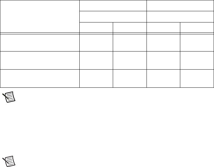
Table A-1. Low Power (100 to 120 VAC, 16 A, 50/60 Hz Input) (Watts)
24U or 40 U Configurations
Low Speed Fan Panel High Speed Fan Panel
Max. Internal Temp Max. Internal Temp
45 °C 50 °C 45 °C 50 °C
40 °C Ambient
(Maximum Mfg Environment)
500 W 1,350 W 1,500 W 1,500 W
28 °C Ambient
(Typical Mfg Environment)
1,870 W 1,870 W 1,620 W 1,620 W
23 °C Ambient
(Typical Room Temperature)
1,870 W 1,870 W 1,620 W 1,620 W
Table A-2. Low Power (200 to 240 VAC, 16 A, 50/60 Hz Input) (Watts)
24U or 40 U Configurations
Low Speed Fan Panel High Speed Fan Panel
Max. Internal Temp Max. Internal Temp
45 °C 50 °C 45 °C 50 °C
40 °C Ambient
(Maximum Mfg Environment)
500 W 1,350 W 1,500 W 1,500 W
28 °C Ambient
(Typical Mfg Environment)
2,550 W 3,400 W 3,540 W 3,540 W
23 °C Ambient
(Typical Room Temperature)
3,400 W 3,790 W 3,540 W 3,540 W

© National Instruments | A-7
ATE Core Configurations RMX-10011 User Manual
Table A-3. Mid Power (200 to 240 VAC, 24 A, 50/60 Hz Input) (Watts)
24U or 40 U Configurations
Low Speed Fan Panel High Speed Fan Panel
Max. Internal Temp Max. Internal Temp
45 °C 50 °C 45 °C 50 °C
40 °C Ambient
(Maximum Mfg Environment)
500 W 1,350 W 1,500 W 1,500 W
28 °C Ambient
(Typical Mfg Environment)
2,550 W 3,400 W 5,460 W 5,460 W
23 °C Ambient
(Typical Room Temperature)
3,400 W 4,300 W 5,460 W 5,460 W
Table A-4. High Power (3 Phase Delta, 200 to 208 VAC, 16 A, 50/60 Hz Input) (Watts)
24U or 40 U Configurations
Low Speed Fan Panel High Speed Fan Panel
Max. Internal Temp Max. Internal Temp
45 °C 50 °C 45 °C 50 °C
40 °C Ambient
(Maximum Mfg Environment)
500 W 1,350 W 1,500 W 1,500 W
28 °C Ambient
(Typical Mfg Environment)
2,550 W 3,400 W 5,440 W 5,440 W
23 °C Ambient
(Typical Room Temperature)
3,400 W 4,300 W 5,440 W 5,440 W
A-8 | ni.com
Appendix A Specifications
Note Refer to Electrical section for the maximum electrical ratings.
Safety
This product is designed to meet the requirements of the following standards of safety for test
and measurement equipment:
• IEC 61010-1, EN 61010-1
• UL 61010-1, CSA C22.2 No. 61010-1
Note For UL and other safety certifications, refer to the product label or the Online
Product Certification section.
Electromagnetic Compatibility
This product meets the requirements of the following EMC standards for electrical equipment
for measurement, control, and laboratory use:
• EN 61326-1 (IEC 61326-1): Class A emissions; Basic immunity
• EN 55011 (CISPR 11): Group 1, Class A emissions
• EN 55022 (CISPR 22): Class A emissions
• EN 55024 (CISPR 24): Immunity
• AS/NZS CISPR 11: Group 1, Class A emissions
• AS/NZS CISPR 22: Class A emissions
• FCC 47 CFR Part 15B: Class A emissions
• ICES-001: Class A emissions
Table A-5. High Power (3 Phase Wye, 220/380 to 240/415 VAC, 16 A, 50/60 Hz Input)
(Watts)
24U or 40 U Configurations
Low Speed Fan Panel High Speed Fan Panel
Max. Internal Temp Max. Internal Temp
45 °C 50 °C 45 °C 50 °C
40 °C Ambient
(Maximum Mfg Environment)
500 W 1,350 W 1,500 W 1,500 W
28 °C Ambient
(Typical Mfg Environment)
2,550 W 3,400 W 6,500 W 8,500 W
23 °C Ambient
(Typical Room Temperature)
3,400 W 4,300 W 8,500 W 8,500 W

© National Instruments | A-9
ATE Core Configurations RMX-10011 User Manual
Note In the United States (per FCC 47 CFR), Class A equipment is intended for use
in commercial, light-industrial, and heavy-industrial locations. In Europe, Canada,
Australia and New Zealand (per CISPR 11) Class A equipment is intended for use
only in heavy-industrial locations.
Note Group 1 equipment (per CISPR 11) is any industrial, scientific, or medical
equipment that does not intentionally generate radio frequency energy for the
treatment of material or inspection/analysis purposes.
Note For EMC declarations and certifications, and additional information, refer to
the Online Product Certification section.
CE Compliance
This product meets the essential requirements of applicable European Directives as follows:
• 2014/35/EC; Low-Voltage Directive (safety)
• 2014/30/EU; Electromagnetic Compatibility Directive (EMC)
Online Product Certification
Refer to the product Declaration of Conformity (DoC) for additional regulatory compliance
information. To obtain product certifications and the DoC for this product, visit
ni.com/
certification
, search by model number or product line, and click the appropriate link in the
Certification column.
Environmental Management
NI is committed to designing and manufacturing products in an environmentally responsible
manner. NI recognizes that eliminating certain hazardous substances from our products is
beneficial to the environment and to NI customers.
For additional environmental information, refer to the Minimize Our Environmental Impact web
page at
ni.com/environment. This page contains the environmental regulations and
directives with which NI complies, as well as other environmental information not included in
this document.

A-10 | ni.com
Appendix A Specifications
Waste Electrical and Electronic Equipment (WEEE)
EU Customers At the end of the product life cycle, all products must be sent to
a WEEE recycling center. For more information about WEEE recycling centers,
National Instruments WEEE initiatives, and compliance with WEEE Directive
2002/96/EC on Waste and Electronic Equipment, visit
ni.com/environment/
weee
.
⬉ᄤֵᙃѻક∵ᶧࠊㅵ⧚ࡲ⊩ ˄Ё
RoHS
˅
Ёᅶ᠋
National Instruments
ヺড়Ё⬉ᄤֵᙃѻકЁ䰤ࠊՓ⫼ᶤѯ᳝ᆇ⠽䋼ᣛҸ
(RoHS)
DŽ݇Ѣ
National Instruments
Ё
RoHS
ড়㾘ᗻֵᙃˈ䇋ⱏᔩ
ni.com/
environment/rohs_china
DŽ
(For information about China RoHS compliance,
go to
ni.com/environment/rohs_china
.)

© National Instruments | B-1
B
Internal Power Cables
This appendix lists the internal power cables for the ATE Core Configurations.
Table B-1. RMX-10011 Internal Power Cables
Part Number Description
785707-01 AC, IEC C20 to NEMA 5-20R, 125 V, 16 A, 0.25 m (US)
785708-01 AC, IEC C19 to NEMA 5-20P, 125 V, 16 A, 2.5 m (US)
785709-01 AC, IEC C20 to IEC C13, 240 V, 10 A (EU), 16 A (UL), 1.5 m (US, EU)
785709-02 AC, IEC C20 to IEC C13, 240 V, 10 A (EU), 16 A (UL), 2.5 m (US, EU)
785710-01 AC, IEC C20 to IEC C19, 240 V, 16 A, 1.5 m (US, EU, China, Korea)
785710-0112 AC, IEC C20 to IEC C19, 240 V, 16 A, 1.5 m (Japan)
785710-02 AC, IEC C20 to IEC C19, 240 V, 16 A, 2.5 m (US, EU, China, Korea)
785710-0212 AC, IEC C20 to IEC C19, 240 V, 16 A, 2.5 m (Japan)
785711-01 AC, IEC C20 to Bare Wire, 240 V, 16 A, 1.5 m (US, EU, China, Korea)
785711-0112 AC, IEC C20 to Bare Wire, 240 V, 16 A, 1.5 m (Japan)
785711-02 AC, IEC C20 to Bare Wire, 240 V, 16 A, 2.5 m (US, EU, China, Korea)
785711-0212 AC, IEC C20 to Bare Wire, 240 V, 16 A, 2.5 m (Japan)
785712-01 AC, IEC C14 to Bare Wire, 240 V, 10 A, 1.5 m (EU, China, Korea)
785712-02 AC, IEC C14 to Bare Wire, 240 V, 10 A, 2.5 m (EU, China, Korea)
785713-01 AC, IEC C14 to IEC C13, 240 V, 10 A, 1.5 m (US)
785713-0112 AC, IEC C14 to IEC C13, 240 V, 10 A, 1.5 m (Japan)
785713-02 AC, IEC C14 to IEC C13, 240 V, 10 A, 2.5 m (US)
785713-0401 AC, IEC C14 to IEC C13, 240V, 10 A, 1.5 m (EU, China, Korea)
785713-0402 AC, IEC C14 to IEC C13, 240V, 10 A, 2.5 m (EU, China, Korea)
785727-01 AC, NEMA 5-20P to Bare Wire, 125 V, 20 A, 1.5m (US)
B-2 | ni.com
Appendix B Internal Power Cables
785727-02 AC, NEMA 5-20P to Bare Wire, 125 V, 20 A, 2.5m (US)
785892-01 AC, IEC C14 to Bare Wire, 240 V, 10 A, 1.5 m (US)
785892-02 AC, IEC C14 to Bare Wire, 240 V, 10 A, 2.5 m (US)
Table B-1. RMX-10011 Internal Power Cables (Continued)
Part Number Description

© National Instruments | C-1
C
NI Services
National Instruments provides global services and support as part of our commitment to your
success. Take advantage of product services in addition to training and certification programs
that meet your needs during each phase of the application life cycle; from planning and
development through deployment and ongoing maintenance.
To get started, register your product at
ni.com/myproducts.
As a registered NI product user, you are entitled to the following benefits:
• Access to applicable product services.
• Easier product management with an online account.
• Receive critical part notifications, software updates, and service expirations.
Log in to your National Instruments
ni.com User Profile to get personalized access to your
services.
Services and Resources
• Maintenance and Hardware Services—NI helps you identify your systems’ accuracy and
reliability requirements and provides warranty, sparing, and calibration services to help you
maintain accuracy and minimize downtime over the life of your system. Visit
ni.com/
services
for more information.
– Warranty and Repair—All NI hardware features a one-year standard warranty that
is extendable up to five years. NI offers repair services performed in a timely manner
by highly trained factory technicians using only original parts at a National
Instruments service center.
– Calibration—Through regular calibration, you can quantify and improve the
measurement performance of an instrument. NI provides state-of-the-art calibration
services. If your product supports calibration, you can obtain the calibration certificate
for your product at
ni.com/calibration.
• System Integration—If you have time constraints, limited in-house technical resources, or
other project challenges, National Instruments Alliance Partner members can help. To learn
more, call your local NI office or visit ni.com/alliance.
C-2 | ni.com
Appendix C NI Services
• Training and Certification—The NI training and certification program is the most
effective way to increase application development proficiency and productivity. Visit
ni.com/training for more information.
– The Skills Guide assists you in identifying the proficiency requirements of your
current application and gives you options for obtaining those skills consistent with
your time and budget constraints and personal learning preferences. Visit ni.com/
skills-guide
to see these custom paths.
– NI offers courses in several languages and formats including instructor-led classes at
facilities worldwide, courses on-site at your facility, and online courses to serve your
individual needs.
• Technical Support—Support at ni.com/support includes the following resources:
– Self-Help Technical Resources—Visit
ni.com/support for software drivers and
updates, a searchable KnowledgeBase, product manuals, step-by-step troubleshooting
wizards, thousands of example programs, tutorials, application notes, instrument
drivers, and so on. Registered users also receive access to the NI Discussion Forums
at
ni.com/forums. NI Applications Engineers make sure every question submitted
online receives an answer.
– Software Support Service Membership—The Standard Service Program (SSP) is a
renewable one-year subscription included with almost every NI software product,
including NI Developer Suite. This program entitles members to direct access to
NI Applications Engineers through phone and email for one-to-one technical support,
as well as exclusive access to online training modules at
ni.com/self-paced-
training
. NI also offers flexible extended contract options that guarantee your SSP
benefits are available without interruption for as long as you need them. Visit
ni.com/ssp for more information.
• Declaration of Conformity (DoC)—A DoC is our claim of compliance with the Council
of the European Communities using the manufacturer’s declaration of conformity. This
system affords the user protection for electromagnetic compatibility (EMC) and product
safety. You can obtain the DoC for your product by visiting
ni.com/certification.
For information about other technical support options in your area, visit ni.com/services,
or contact your local office at ni.com/contact.
You also can visit the Worldwide Offices section of
ni.com/niglobal to access the branch
office websites, which provide up-to-date contact information, support phone numbers, email
addresses, and current events.

© National Instruments | G-1
Glossary
Symbol Prefix Value
ppico10
-12
nnano10
-9
μmicro10
-6
m milli 10
-3
k kilo 10
3
Mmega10
6
Ggiga10
9
Ttera10
12
Symbols
°Degrees.
≥ Equal or greater than.
≤ Equal or less than.
%Percent.
A
AAmperes.
AC Alternating current.
ANSI American National Standards Institute.
Auto Automatic fan speed control.
AWG American Wire Gauge.
Glossary
G-2 | ni.com
B
backplane An assembly, typically a printed circuit board, with connectors
and signal paths that bus the connector pins.
BNC Bayonet Neill Concelman connector; a commonly used coaxial
connector.
C
C Celsius.
cfm Cubic feet per minute.
CFR Code of Federal Regulations.
cm Centimeters.
CompactPCI An adaptation of the Peripheral Component Interconnect (PCI)
Specification 2.1 or later for industrial and/or embedded
applications requiring a more robust mechanical form factor than
desktop PCI. It uses industry standard mechanical components
and high-performance connector technologies to provide an
optimized system intended for rugged applications. It is
electrically compatible with the PCI Specification, which enables
low-cost PCI components to be utilized in a mechanical form
factor suited for rugged environments.
CSA Canadian Standards Association.
D
daisy-chain A method of propagating signals along a bus, in which the
devices are prioritized on the basis of their position on the bus.
DB-9 A 9-pin D-SUB connector.
DC Direct current.
DoC Declaration of Conformity.
D-SUB Subminiature D connector.
ATE Core Configurations RMX-10011 User Manual
© National Instruments | G-3
E
efficiency Ratio of output power to input power, expressed as a percentage.
EIA Electronic Industries Association.
EMC Electromagnetic Compatibility.
EMI Electromagnetic Interference.
F
FCC Federal Communications Commission.
filler panel A blank module front panel used to fill empty slots in the chassis.
G
g (1) grams; (2) a measure of acceleration equal to 9.8 m/s
2
.
GPIB General Purpose Interface Bus (IEEE 488).
g
RMS
A measure of random vibration. The root mean square of
acceleration levels in a random vibration test profile.
H
hr Hours.
Hz Hertz; cycles per second.
I
IEC International Electrotechnical Commission; an organization that
sets international electrical and electronics standards.
IEEE Institute of Electrical and Electronics Engineers.
I
MP
Mainframe peak current.
Glossary
G-4 | ni.com
in. Inches.
inhibit To turn off.
J
jitter A measure of the small, rapid variations in clock transition times
from their nominal regular intervals. Units: seconds RMS.
K
kg Kilograms.
km Kilometers.
L
lb Pounds.
LED Light emitting diode.
line regulation The maximum steady-state percentage that a DC voltage output
will change as a result of a specified change in input AC voltage
(step change from 90 to 132 VAC or 180 to 264 VAC).
load regulation The maximum steady-state percentage that a DC voltage output
will change as a result of a step change from no-load to full-load
output current.
M
m Meters.
MHz Megahertz. One million Hertz; one Hertz equals one cycle per
second.
mi Miles.
ms Milliseconds.
ATE Core Configurations RMX-10011 User Manual
© National Instruments | G-5
MTBF Mean time between failure.
MTTR Mean time to repair.
N
NEMA National Electrical Manufacturers Association.
NI National Instruments.
P
power supply shuttle A removable module that contains the chassis power supply.
PXI PCI eXtensions for Instrumentation.
PXI_CLK10 10 MHz PXI system reference clock.
R
RH Relative humidity.
RMS Root mean square.
S
s Seconds.
skew Deviation in signal transmission times.
slot blocker An assembly installed into an empty slot to improve the airflow
in adjacent slots.
standby The backplane is unpowered (off), but the chassis is still
connected to AC power mains.
System controller A module configured for installation in Slot 1of a PXI chassis.
This device is unique in the PXI system in that it performs the
system controller functions, including clock sourcing and
arbitration for data transfers across the backplane. Installing
such a device into any other slot can damage the device, the
PXI backplane, or both.
Glossary
G-6 | ni.com
system reference
clock
A 10 MHz clock, also called PXI_CLK10, that is distributed to
all peripheral slots in the chassis, as well as a BNC connector
on the rear of chassis labeled 10 MHz REF OUT. The system
reference clock can be used for synchronization of multiple
modules in a measurement or control system. The 10 MHz REF
IN and OUT BNC connectors on the rear of the chassis can be
used to synchronize multiple chassis to one reference clock. The
PXI backplane specification defines implementation guidelines
for PXI_CLK10.
System Timing slot This slot is located at slot 4 and has dedicated trigger lines to
other slots.
T
TTL Transistor-transistor logic.
U
UL Underwriter’s Laboratories.
V
V Volts.
VAC Volts alternating current.
V
pp
Peak-to-peak voltage.
W
WWatts.

© National Instruments | I-1
Index
A
AC Mains cables, 3-1
AC power cables (table), 3-2
B
block diagrams, 4-5
C
cables, power (table), 3-2
circuit protection, 3-4
cleaning
air intake filters, 5-2
exterior, 5-1
configuration, 2-1
crate
(figure), 2-1
dimensions, 2-2, 2-3
E
electromagnetic compatibility, A-8
emergency power off (EPO), 4-4
environmental management specifications,
A-9
Ethernet port, 4-3
G
grounding, 3-4
I
installation, 2-1
internal power cables, B-1
introduction
nomenclature, 1-1
overview, 1-1
L
loading, 2-5
M
main power switch, 4-4
maintenance, 5-1
mechanical stability, 2-5
O
operator safety information, 3-3
P
packaging information, 2-1
power
cables (table), 3-2
connection, 2-6
off, 3-2
on, 4-7
recommendations, 2-6
states, 4-6
power cables (table), 3-2
power distribution unit (PDU), 4-3
power entry panel (PEP), 4-1
R
removing power, 3-2
replacement parts, 5-2
required tools, 2-3
S
safety
features, 3-3
operator, 3-3
requirements, 3-1
specifications, A-8
site requirements, 2-6
specifications, A-1
CE compliance, A-9
dimensions, A-1, A-2
electrical, A-2
electromagnetic compatibility, A-8
environment, A-2
mechanical, A-1
safety, A-8
