
Manual
Operational &
Maintenance
Products:
Installation Site
Contractor
Architect
Distributor
Enter Product Category / Model Number
Enter Project Name/Site info
Enter Contractor Firm Name here
Enter Architect Firm Info Here
Overhead Door Company of ABC
123 Eagle Street
Eagle Town, TX 75067

Dear Customer:
Thank you for choosing RXUFRPSDQ\as your cust
om door installation specialist.
The Operation
and Maintenance Manual, which is enclosed, has been supplied by Overhead Door
Corporation to meet your needs as our customer. Appropriate information for the products installed
has been compiled in this manual for your use. We recommend compliance with all of the safety
information provided within the manual.
We strongly recommend implementing a preventative maintenance program. Benefits of properly
maintaining your door system include:
• Increased operational efficiency and reliability.
• Extended useful life of your equipment.
• Increased probability of dependable equipment performance.
• Elimination of non-budgeted maintenance cost for door service.
As an Overhead Door distributor, we offer you complete product support for your service and
maintenance needs. Do not hesitate to call us for assistance.
We hope that you will also continue to consider RXUFRPSDQ\ for your fut
ure product and
installation needs.
We are firmly committed to providing the finest in Overhead Door products,
accessories, and a level of customer support unmatched in the industry.
Sincerely,
Enter Company Name Ex: Overhead Door Company of
Enter City, ST zip code
Enter Company Name Ex: Overhead Door Company of
Enter Street Address

©Overhead Door Corporation Operation & Maintenance Manual: Commercial Operators
Operation & Maintenance Manual
Commercial Operators
Table of Contents
Section 1 General Information
Section 2 Preventative Maintenance
Section 3 Installation Instructions
Section 4 Warranty

©Overhead Door Corporation Operation & Maintenance Manual: Commercial Operators
GENERAL
INFORMATION
OVERHEAD DOOR CORPORATION
Overhead Door Corporation, based in Dallas, Texas, is a leading single-source
manufacturer of integrated door and operator systems for commercial and residential
applications.
Overhead Door is the door solutions provider that delivers expert service and the
highest level of performance and reliability. Our comprehensive product line
encompasses a wide variety of commercial door solutions including: commercial
operators, commercial sectional and rolling service doors, advanced performance rolling
doors, and security grilles.
With our nationwide network of more than 400 authorized distributors, we are a leading
provider of overhead and garage door systems, and we continue to lead the way with
reliable solutions and unmatched professional installation, service and support that
keeps customers coming back. The brand trusted for over 90 years, Overhead Door
gives home and business owners confidence and peace of mind.
To locate a distributor:
From the United States, call 1-800-929-3667 (DOOR)
International: 1-717-248-0131
http://www.overheaddoor.com/Pages/distributor-locator.aspx
Contact Information:
Overhead Door Corporation
2501 S. State Hwy. 121, Suite 200
Lewisville, TX 75067
Telephone: 1-800-275-3290
www.overheaddoor.com

©Overhead Door Corporation Operation & Maintenance Manual: Commercial Operators
PREVENTATIVE
MAINTENANCE

©Overhead Door Corporation Preventative Maintenance
BENEFITS OF PREVENTATIVE MAINTENANCE PROGRAM
Increase operational efficiency, safety and reliability
Extend useful life of your equipment
Reduce probability of equipment malfunctioning
Decrease costly downtime
Decrease long-term repair expense
Priority scheduling for service
Establish relationship with experienced, service-oriented professionals

©Overhead Door Corporation Preventative Maintenance
SCOPE OF WORK FOR ELECTRIC OPERATORS
For the period _______________, 20__, through _______________, 20__, the following services and
inspections will be provided as part of the Preventative Maintenance Program for operator(s):
ELECTRIC OPERATORS:
1) Inspect and adjust limit switches.
2) Inspect and adjust belts.
3) Inspect and adjust brake.
4) Inspect gear reducer.
5) Inspect operator mounting.
6) Inspect and test disconnect.
7) Inspect and lubricate roller chain.
8) Inspect and tighten all sprockets.
9) Inspect safety labels, placement and condition.

©Overhead Door Corporation Operation & Maintenance Manual: Commercial Operators
INSTALLATION
INSTRUCTIONS
NOT FOR RESIDENTIAL USE
110929.0001
EN 36221
This Installation Manual provides the information required to install, troubleshoot and maintain an
RMX™ Commercial/Industrial Door Operator.
SIDEMOUNT
07/30/09

Table of Contents
Section 1 How to use this manual .......................................1.1
Section 2 Safety Information & Instructions.....................2.1
Section 3 General Information ..............................................3.1
Section 4 Installation.................................................................4.1-4.8
Direct Couple ...........................................................4.2-4.3
Chain Couple (optional).......................................4.4-4.6
Clutch and Brake Adjustment............................4.7
Hand Chain Installation........................................4.8
Section 5 Wiring..........................................................................5.1-5.7
Line Voltage Wiring................................................5.1
Low Voltage Control Wiring................................5.2
External Wire Diagram..........................................5.3
Wall Control ..............................................................5.4
Interlock Switches ..................................................5.5
Radio Control & Photocell Wiring.....................5.6
Sensing Edge Wiring .............................................5.7
Section 6 Operator Setup Procedures ................................6.1-6.8
Control Panel............................................................6.1
Setting Constant Contact ....................................6.2
Setting Limit Travel ................................................6.3
Setting Limit Overrun ...........................................6.4
Using Series II Safe-T-Beam® ..............................6.5
Max Run Timer.........................................................6.6
Setting the Mid-Stop.............................................6.7
Changing Open & Close Modes ........................6.8
Section 7 Special Operator Features ..........................................7.1-7.2
Operator Cycle Count & Firmware Version...........7.1
Operator Type..................................................................7.2
Section 8 Troubleshooting.............................................................8.1-8.4
Display Operatio.............................................................8.1
Error Codes.......................................................................8.1-8.2
Run Codes.........................................................................8.2-8.3
LED Indicators .................................................................8.3
Section 9 Service & Maintenance ................................................9.1
Section 10 Appendix A.............................................................. 10.1-10.11
Operator w/Hoist Exploded View........................10.1
Operator w/Hoist Parts List....................................10.2
Operator w/Release Exploded View ...................10.3
Operator w/Release Parts List...............................10.4
Shaft Assemblies .......................................................10.5
Shaft Parts List............................................................10.6
Electric Box Exploded View...................................10.7
Electric Box Parts List...........................................10.8-10.9
Appendix B, Screw Terminal Assignments............10.10
Appendix C, LCD Display Readouts................10.11-10.13
Run Codes....................................................................10.11
Error Codes..........................................................10.12-10.13
Appendix D
Safe-T-Beam® Monitored Photocell
Troubleshooting Chart ............................................10.14
Section 11 Warranty............................................................................11.1
TOC
www.overheaddoor.com 07/30/09

FOR ASSISTANCE CALL 1-800-275-6187
1.1
Section 1: How to use this manual
Section 2
Provides important defining information related to safety terminology used throughout this manual, as
well as saf
ety related instructions which must be followed at all times while doing any
steps/tasks/instructions detailed in this manual.
Section 3
Details pre-installation concerns/issues/decisions that are recommended to be considered and/or
r
esolv
ed prior to beginning any commercial door operator installation.
Sections 4-6
Provide step by step installation and set-up instructions for the RMX™ commercial door operator. Each
section is wr
itten such that it must be followed in a step by step order to complete a successful
installation.
Sections 7-8
Detail important features and troubleshooting information for typical installation and normal operations
tha
t ma
y occur.
Sections 9-11
Pr
ovide related information on service and maintenance items, operator drawings for use in
troubleshooting and service activities, along with important warranty and returned goods policy
information.
The 11 sections of this Installation Manual provide the information required to install,
troubleshoot and maintain an RMX™ commercial/industrial door operator.
Failure to correctly perform all steps in sections 4-6 can result in serious injury or death.
WARNING
www.overheaddoor.com 07/30/09
2.1
Section 2: Safety Information & Instructions
WARNING
Overhead Doors are large, heavy objects that move with the help of springs under high tension and electric motors. Since
moving objects, springs under tension, and electric motors can cause injuries, your safety and the safety of others depend on
you reading the information in this manual. If you have any questions or do not understand the information presented, call
your nearest service representative. For the number of your local Overhead Door Dealer, call 800-929-3667, and for Overhead
Door Factory Technical Advice, call 800-275-6187.
In this Section and those that follow, the words Danger, Warning, and Caution are used to stress important
safety information.The word:
:
DANGER indicates an imminently hazardous situation which, if not avoided, will result in death or serious injury.
WARNING indicates a potentially hazardous situation which, if not avoided, could result in death or serious injury.
CAUTION indicates a potentially hazardous situation which, if not avoided, may result in injury or property damage.
The word NOTE is used to indicate important steps to be followed or important considerations.
POTENTIAL
EFFECT
PREVENTION
HAZARD
MOVING DOOR
Do Not operate unless the doorway is in sight and free of
obstructions. Keep people clear of opening while door is moving.
Do Not allow children to play with the door operator.
Do Not change operator c
on
trol to momentary contact unless an
external reversing means is installed.
Do Not operate a door that jams or one that has a broken spring
Could result
in Serious
Injury
or Death
Turn off electrical power before removing operator cover.
When replacing the cover, make sure wires are not pinched or
near moving parts.
Operator must be electrically grounded.
ELECTRICAL
SHOCK
Do Not try to remove, repair or adjust springs or anything to
which door spr
ing parts are fastened, such as, wood block,
steel bracket, cable or any other structure or like item.
Repairs and adjustments must be made by a trained service
representative using proper tools and instructions.
HIGH SPRING
TENSION
Could result
in Serious
Injury
or Death
Could result
in Serious
Injury
or Death
IMPORTANT
READ PRIOR TO ANY DOOR OPERATION
WARNING
WARNING
WARNING
1. Read manual and warnings carefully.
2. Keep the door in good working
condition. Periodically lubricate all
moving parts of door.
3. If door has a sensing edge, check
operations monthly. Make any necessary
repairs to keep it functional.
4. AT LEAST twice a year, manually
operate door by disconnecting it from
the operator. The Door should open and
close freely. If it does not, the door must
be taken out of service and a trained
service representative must correct the
condition causing the malfunction.
5. The Operator Motor is protected against
overheating by an internal thermal
protector. If the operator ceases to
function because motor protector has
tripped, a trained service technician
may need to correct the condition which
caused the overheating. When motor has
cooled, thermal protector will
automatically reset and normal
operation can be resumed.
6. In case of power failure, the door can be
operated manually by pulling the release
cable to disconnect the operator drive
system.
7. Keep instructions in a prominent
location near the pushbutton.
www.overheaddoor.com 07/30/09

3.1
Section 3: General Information
Job Site Issues to Consider/Concerns
The following list of items should be considered prior to selecting an operator for a given job site.
• Available power supply.
• Type of door.
• Potential operator mounting obstructions. Items to consider include, but are not limited to: side room, room above door shaft,
room below door shaft, available mounting surface integrity, power supply location, and convenient chain hoist and release
cable positioning.
• Size of door for appropriate operator torque and door travel speed selection.
• Operator mounting environment. Items to consider include operator location, dampness of location, dustiness of the location
and corrosiveness of the location.
• Door activation needs/requirements. Examples include 3 button control stations, 1 button control stations, radio controls, pull
cords, loop detectors, photoelectric controls, key switches, etc. See “Entrapment Protection” section below.
• Interlock switches are required under certain conditions for doors with pass doors and door locks. See Section 5.5 below.
• Accessory equipment. Examples include reversing edges and/or photocell beams, which are required for doors set to operate as
momentary contact, auxiliary control relays, warning lights, etc.
See “Entrapment Protection” section below.
Entrapment Protection Recommendations
O
verhead Door Corporation recommends the installation of a fail safe external reversing device (such as a reversing edge or photocell
system, etc.) on all electronically operated commercial doors. If such a reversing device is not chosen, then the operator must be installed
with only a constant contact control switch for operation.
NOTE: A monitored 2-wire reversing edge or sensing edge can be installed using the optionally available Timer Close Module (TCM) P/N OPABTCX.S.
WARNING:
DO NOT apply line voltage until instructed to do so.
CAUTION:
Check working condition of door before installing the operator. Door must be free from sticking and binding. If equipped, deactivate
any door locking device(s). Door repairs and adjustments, including cables and spring assemblies MUST be made by a trained
service representative using proper tools and instructions.
www.overheaddoor.com 07/30/09

4.1
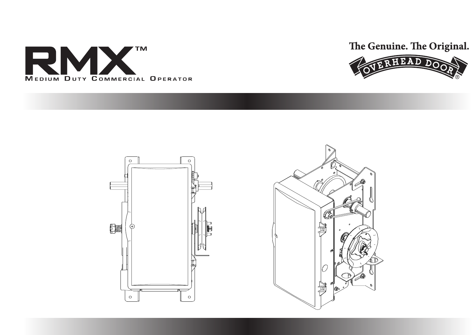
Figure 1
RELEASE CORD
RELEASE CORD
JACKSHAFT VERSION
HOIST VERSION
Figure 1A
NOTE: The Model RMX™ Side Mount is designed to be mounted on
either side of the door with the motor down and the cover to the front.
Fig. 1. An alternate position is horizontal with the motor to the back and
the cover facing up. No other mounting position is acceptable.
NOTE: Hoist versions will only have the hoist mounted on the right
hand side and cannot be reversed.
NOTE: Units without Hoist will not have a pocket wheel as shown in the
following diagrams.
RELEASE VERSION
The release cable must be installed on the operator before the
unit is installed, Fig. 1A.
Section 4: Installation
www.overheaddoor.com 07/30/09
1) The RMX™ side mount can be directly coupled to the door
shaft when the centerline of shaft is 3-3/4" OR 5", however,
some installations will require chain and sprocket coupling
to the door shaft. Fig 6, page 4.4.
Some reasons for chain coupling are:
•
Insufficien
t side room or other interference.
• Change door speed for standard lift doors or full vertical
doors.
• Centerline of door shaft different than 3-3/4" or 5".
2) Determine if centerline of door shaft is 3-3/4" or 5".
3) Adjust mounting feet on operator to required centerline
distance.Tighten securely. Fig. 2.
4) Slide coupling ont
o op
erator shaft on desired side
(Do N
ot mount hoist model on lef
t). Fig. 3.
5) Raise operator into position.
6) Slide coupling onto door counterbalance shaft. Do NOT
secure coupling at this time.
7) Make certain operator and door shafts are in alignment.
8) Secure operator to the wall or mounting pads using 4 outer
most mounting holes.
9) Secure Coupler
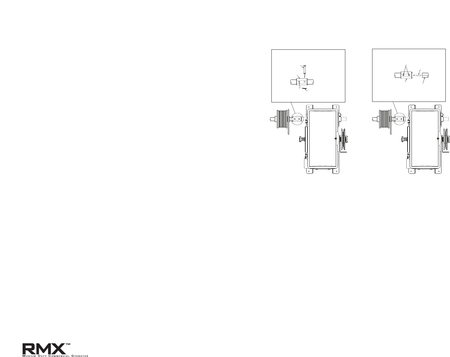
NOTE:The output shaft of the RMX™ can be moved from side to side to
increase/decr
ease the eff
ective shaft length for direct coupling.This is
done by loosening the set screws in the limit sprocket and shaft
set collars, moving the shaft and retightening all the set screws. Fig.4.
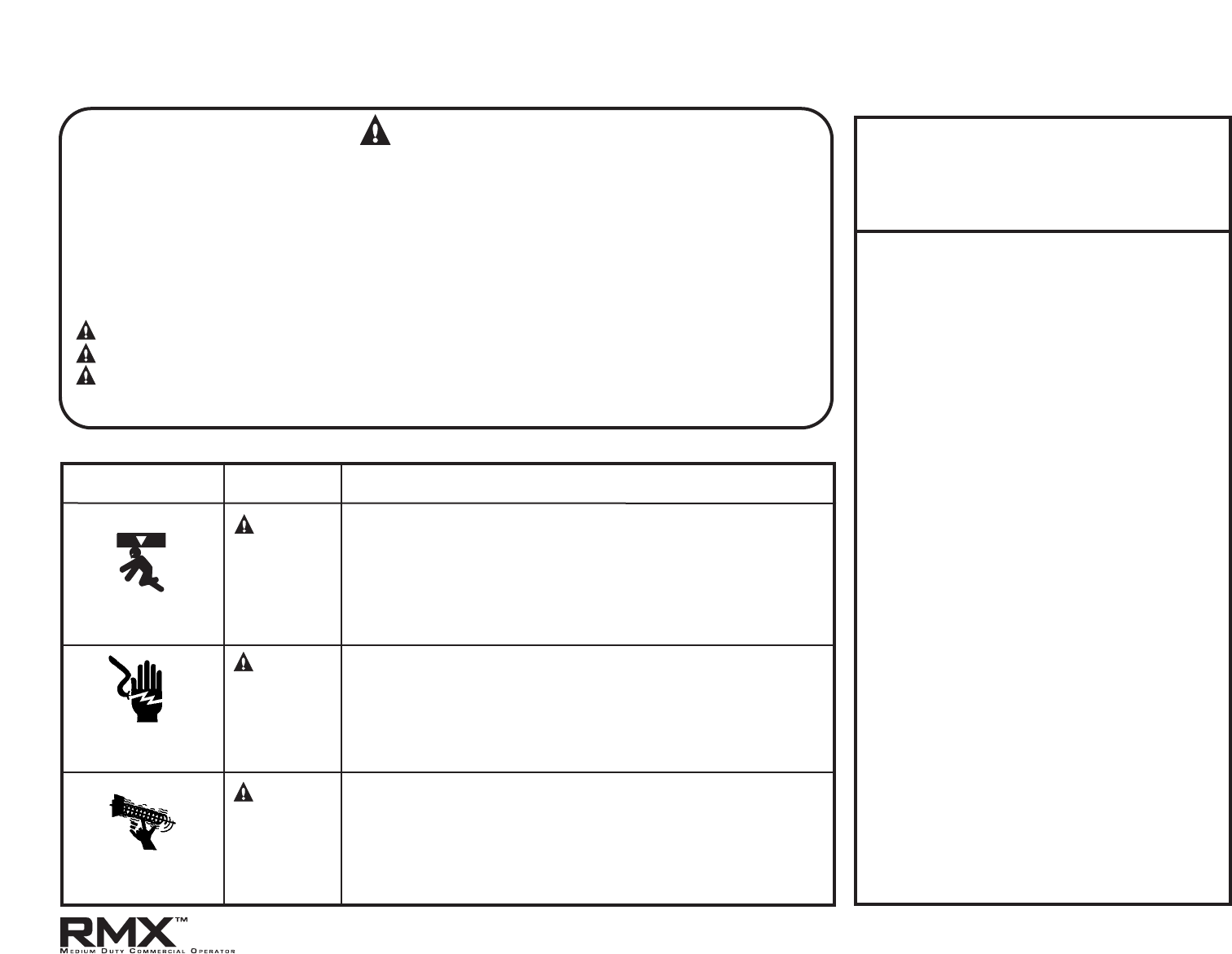
4.2
Direct Couple
5"
CENTERLINE
3-3/4"
CENTERLINE
Note Mounting
Pad Bolt Locations
Figure 2
Figure 3
No Hoist for Left
mounted unit.
Jackshaft model only
.
Figure 4
Set collar
set screws
Limit sprocket
set screw
www.overheaddoor.com 07/30/09
Hollow Door Shaft:
1) Use coupling as a drill guide and drill a 3/8" diameter hole
through door shaft and other side of coupling. Fig. 5.
2) Secure coupling to door shaft with 3/8" x 1-3/4" clevis pin
and 1/16" x 3/4" cotter pin from hardware kit.
Solid Door Shaft:
1) R
aise door until keyway of door shaft is in line with keyway
of operator coupling.
2) Insert key. If keyway on door shaft restricts insertion, move
coupling toward operator, insert key and return.
Operator Output Shaft:
1) S
ecure coupling to operator with set screws provided.
NOTE: Hoist models include an interlock swit
ch to prevent electrical
operation when hoist is engaged. See Section 5.5 below.
4.3
Direct Couple
DRILL 3/8" HOLE
THRU SHAFT &
COUPLER FOR
CLEVIS PIN
CLEVIS
PIN
COUPLER
SET SCREW
COTTER PIN
SET SCREWS
COUPLER
KEY
DOOR
SHAFT
Hollow Shaft
Solid Shaft
Figure 5
www.overheaddoor.com 07/30/09

The RMX™ Side Mount Operator can be assembled for right hand
mounting above or below the door shaft. Fig. 6A.
NOTE:The operator output shaft extends 3-7/8" on each side of the
RMX™ op
er
ator frame.
1) Attach 16 tooth sprocket to operator output shaft.
2) Align keyways and insert key into sprocket and door shaft
keyway. Do not tighten set screw at this time.
3) Attach 16 tooth door sprocket to door shaft. Do not tighten
at this time.
4) Assemble chain using chain connecting link.
5) Place assembled chain over door shaft sprocket.
6) Raise or lower operator to remove slack from the chain.
7) Be certain operator output shaft is parallel with door shaft.
8) Align chain and secure operator to wall or mounting pad.
Fig.6
B.
9) T
ighten operator sprocket set screws.
INSTALLATION TIP:
While sprocket set screws are loose,
if p
ossible, manually operate door to
help align chain. A properly tensioned drive chain should deflect no
more than 1/2" when thumb pressure is applied mid-way between the 2
sprockets.While there is no hard and fast rule governing chain tension, it
must be tight enough to prevent clicking, popping and jumping the
teeth of the sprocket.The 1/2" guideline will insure sufficient tension.
NOTE: If using slotted mounting holes to mount unit
,
you must use at
least 2 lockdown holes in opposite corners to firmly mount unit to wall.
Fig. 5B.
4.4
Chain Couple (optional)
CHAIN COUPLING KIT CHART
KIT P/N RATIO OPENER SHAFT SPROCKET DOOR SHAFT SPROCKET
109049.0001 1:1 109047.0001 16T 109047.0002 16T
109049.0002 21:16 109048.0001 21T 109047.0002 16T
SPEED-UP
Figure 6B
Figure 6A
www.overheaddoor.com 07/30/09
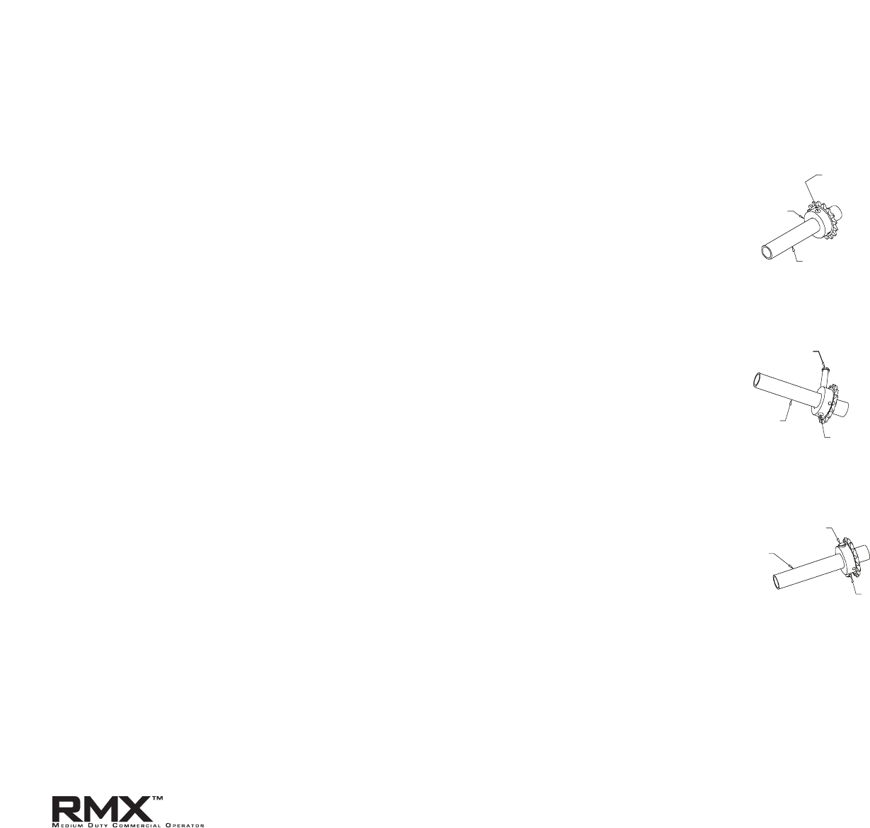
For Hollow Counterbalance Door Shaft:
1) Use non-threaded hole in door shaft sprocket as a guide and
drill a 3/8" diameter hole through one side of the door shaft.
Fig. 7A.
2)
Insert clevis pin through sprocket and shaft to hold sprocket
in position.
3) Drill through opposite side of shaft to obtain proper hole
alignment. Fig. 7B.
4)
Inser
t clevis pin through both holes and secure with cotter pin.
Fig. 7C.
For Solid Counterbalance Door Shaft:
1) Insert k
ey into door shaft keyway.
2) Slide sprocket into place and secure with set screws.
To Complete the Installation:
If needed, realign operator spr
ocket with door sprocket. If you have
excessive door shaft movement, an optional chain tension plate is
available. Fig.8, pg 4.6.
4.5
Chain Couple (optional)
SPROCKET HUB
DRILL HOLE
IN THIS SIDE
OF SHAFT
DOOR SHAFT
(TUBE)
CLEVIS PIN
DRILL HOLE IN
OPPOSITE SIDE
OF SHAFT
DOOR SHAFT
(TUBE)
DOOR SHAFT
(TUBE)
CLEVIS PIN
COTTER PIN
A
B
C
Figure 7A
Figure 7B
Figure 7C
www.overheaddoor.com 07/30/09
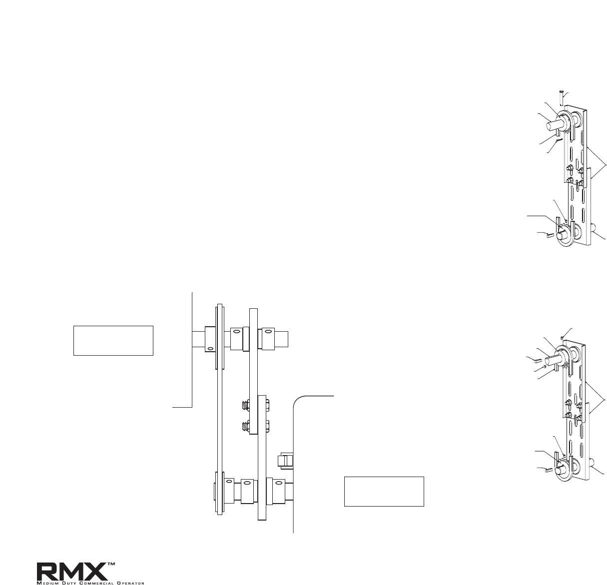
Bracket is available as an optional kit, P/N 111005.0001.S
Installation of optional chain spreader bracket: Fig 8A & 8B.
1) P
lace sprocket, upper plate and bearing assembly on door shaft
as shown.
2) Place lower plate, bearing assembly and sprocket on operator
shaft as shown.
3) Install door and operator sprockets and chain assembly as
described in steps 2 through 4 in preceding instructions.
4) Install bolts and nuts through plates.
5) Tighten and align chain and plate and secure operator to wall.
6) Tighten spreader bracket bolts.
4.6
Chain Couple (optional)
Spreader Bracket
DOOR SHAFT
SPROCKET
DOOR SHAFT
KEY
SET SCREW
CHAIN
SET SCREW
CHAIN
TENSION
PLATE
OPERATOR
OUTPUT
SHAFT
KEY
SET SCREW
OPERATOR
SHAFT
SPROCKET
DOOR SHAFT
SPROCKET
DOOR SHAFT
CHAIN
CHAIN
TENSION
PLATE
OPERATOR
OUTPUT
SHAFT
KEY
SET SCREW
OPERATOR
SHAFT
SPROCKET
COTTER PIN
CLEVIS PIN
HOLLOW COUNTERBALANCE
DOOR SHAFT
SOLID COUNTERBALANCE
DOOR SHAFT
Figure 8B
OPERATOR
SHAFT
DOOR
SHAFT
Figure 8A
SPROCKET
GOES ON FIRST
SPROCKET
GOES ON LAST
www.overheaddoor.com 07/30/09
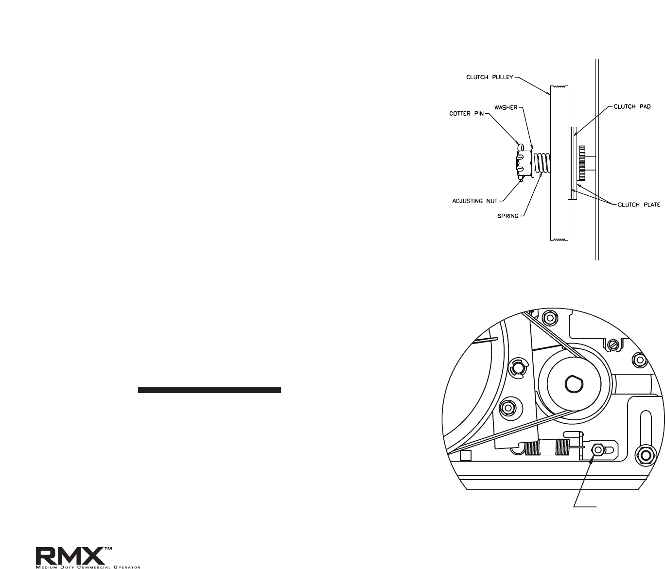
The MX Operators have a friction style clutch that can be adjusted.
NOTE:The clutch is intended to provide protection for the door, the
oper
ator and associated equipment. It is not intended for entrapment
protection.
To Adjust the Clutch
1) Decrease the tension on the clutch until the operator will not lift
the do
or
.
• Turning the adjustment castle nut counter-clockwise will
decrease tension and clockwise will increase tension.
2) Gradually increase tension until the operator will perform a
complete open and close cycle without clutch slippage.
3) Insert a cotter pin through the adjustment castle nut and bend a
leg of the cotter pin to hold it in place.
NOTE: Periodically check the system for proper clutch action. If clutch
star
ts t
o slip after working properly for some time , check manual
operation of door BEFORE adjusting clutch.The door may not be
operating freely or the counterbalance spring may need adjusting.
Repairs and adjustments must be performed by a trained service
representative using proper tools and instructions.
1) Loosen the Adjustment Bracket Lock Nut/Bolt.
2) Slide the Adjustment Bracket as needed to reach the desired
spring tension.
• When properly adjusted, the pivot arm should
move with very little effort.
3) Re-tighten the Adjustment Bracket Lock Nut/Bolt.
4.7
Clutch Adjustment Fig. 9
Brake Adjustment Fig. 10
BRAKE ADJUSTMENT
LOCK NUT AND BOLT
Figure 9
Figure 10
www.overheaddoor.com 07/30/09
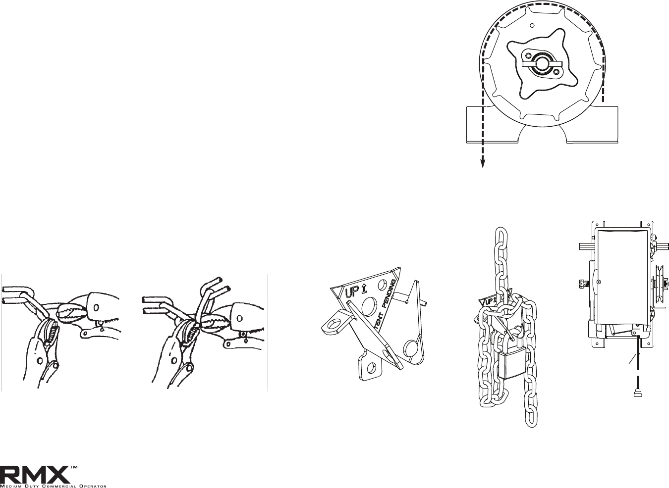
4.8
1) Route the hand chain through the chain guide, around the
pocket wheel and back through the chain guide. Fig.11.
2) Connect the hand chain ends together as shown in Fig 12.
by twisting open the last link on one end of the chain, and
slipping the last link on the opposite end onto the open link.
3) Twist open link closed again.
4) Mount chain keeper to wall in line with chain approximately
4 feet from floor.
5) Loop chain around keeper as shown. Fig. 13. Optional Padlock
not provided
.
6) Install release cable. Fig. 14.
NOTE:T
o insure smooth operation, make sure there are no twist in the
hand chain before connecting the link ends together.
Hand Chain & Keeper
Figure 11
Figure 12
Figure 13
Figure 14
www.overheaddoor.com 07/30/09
RELEASE CORD
5.1
Section 5: Wiring
Line Voltage Wiring
Fig. 1
OPEN CLOSE
STOP GND 1-BTN
N/O
SAFETY
N/O
SAFETY
ODC
STB
ODC
STB
EXT
INTLK
EXT
INTLK
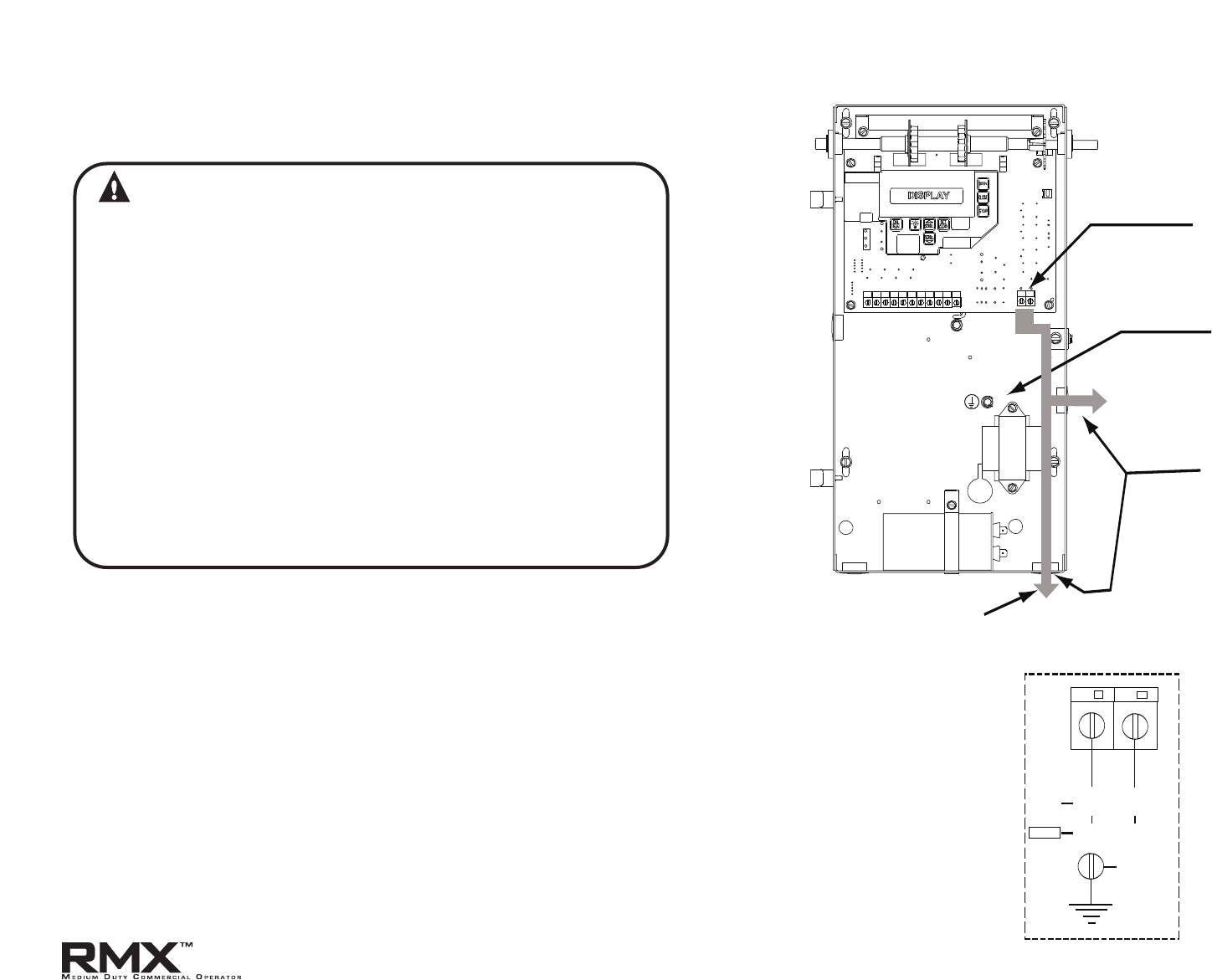
L1
N
HIGH VOLTAGE
INPUT PLUGS
LINE INPUT
TERMINALS
LINE
GROUND
ROUTE LINE VOLTAGE
WIRING IN SHADED
AREA AS SHOWN
Figure 1
L1/L1
N/L2
GND
LINE IN
POWER CONNECTIONS
120V
240V
LINE
(HOT)
NEUTRAL
LINE 1
LINE 2
Figure 2
WARNING
• DO NOT apply power to operator until instructed to do so.
• Overhead Door Corporation recommends that line voltage
wiring be performed by a qualified electrician.
• Be sure that electrical power has been disconnected from
the input power wires being connected to the operator
prior to handling these wires. An appropriate lock-out /
tag-out procedure is recommended.
• Line voltage wiring must meet all local building codes.
• Make sure operator voltage, phase and frequency
nameplate ratings are identical to the job site line
voltage ratings.
• Input power wiring must be properly sized for the
operators amperage rating located on the nameplate.
• To reduce the risk of electric shock, make sure the chassis
of this unit is properly grounded.
1) Remove LINE VOLTAGE INPUT PLUG and install proper
fittings and 1/2"conduit.
2) Route proper LINE VOLTAGE wires into operator.
3) Locate LINE INPUT terminals on circuit board. Using
correct connectors, attach wires to LINE INPUTS, and GROUND
terminal. Fig. 2.
•
Keep low voltage and line voltage wires separate.
• Route all line voltage wires as shown.
• Plug all unused conduit holes.
www.overheaddoor.com 07/30/09
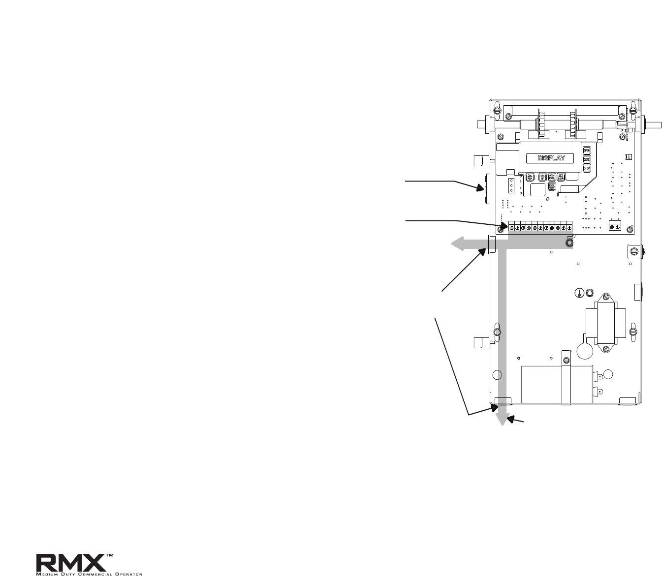
1) Connect all LOW VOLTAGE control circuit wires to this side
of unit using 1/2" conduit or flexible convoluted tubing.
• Keep low voltage and line voltage wires separate.
• Route all low voltage control wiring as shown. This includes
all control circuit wires such as wall controls, timers and single
button input devices as well as radio control and safety circuit
wiring. See Figs 2 through 10 in this section.
• Plug all unused conduit holes.
5.2
Low Voltage Control Wiring (general) Fig. 3
OPEN CLOSE
STOP GND 1-BTN
N/O
SAFETY
N/O
SAFETY
ODC
STB
ODC
STB
EXT
INTLK
EXT
INTLK
L1
N
RADIO
CONTROL
TERMINALS
LOW VOLTAGE
CONTROL WIRE
TERMINALS
LOW
VOLTAGE
INPUT
PLUGS
ROUTE LOW VOLTAGE
WIRING IN SHADED
AREA AS SHOWN
Figure 3
NOTE: For a detailed description of control wire terminals see
Appendix B.
www.overheaddoor.com 07/30/09
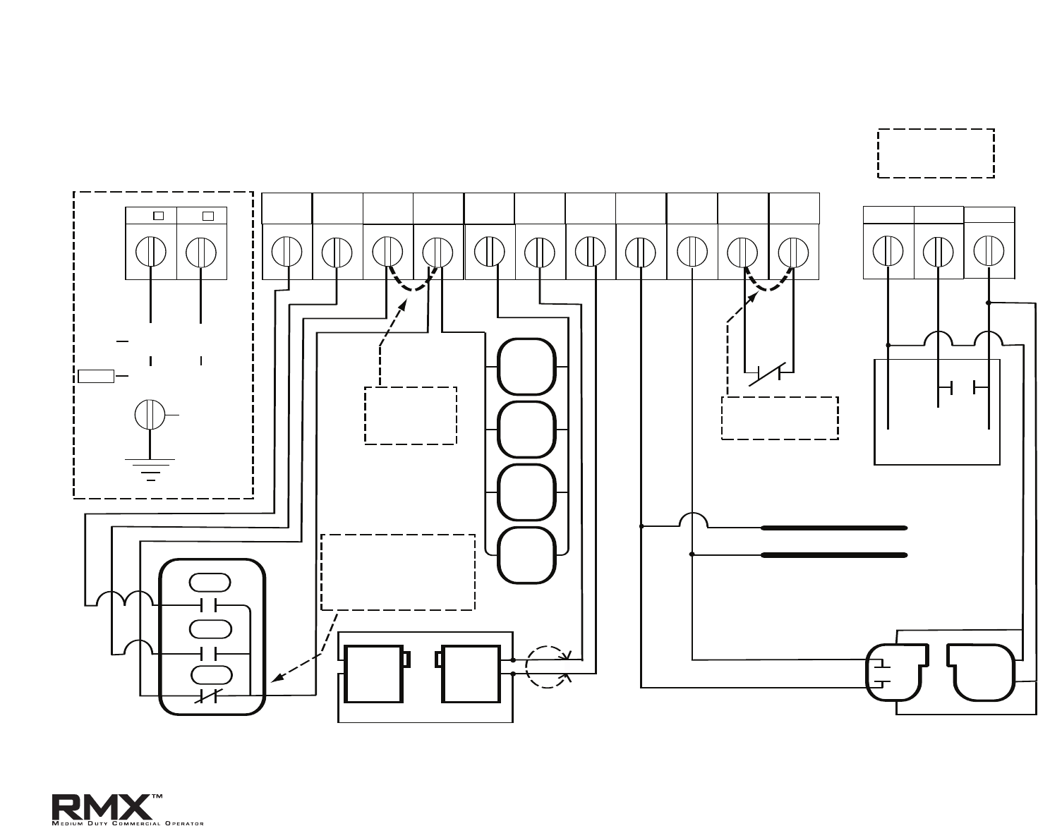
5.3
External Wire Diagram
See Appendix B for detailed description of terminals.
L1/L1
N/L2
GND
PWR
RAD GND
OPEN CLOSE
STOP GND 1-BTN
N-O
SAFETY
N-O
SAFETY
ODC
STB
ODC
STB
EXT
INTLK
EXT
INTLK
OPEN
CLOSE
STOP
1-BTN
STATION
KEY
SWITCH
STATION
CARD
READER
O/C
PULL
SWITCH
RELAY
GND
NOM
+ 24VDC
SENSING EDGE SWITCH
N/O
N/O
N/O
N/O
3-BUTTON
STATION
SERIES II SAFE-T-BEAM
®
(STB)
+
-
+
-
THRU-BEAM
PHOTOCELLS
RADIO
REMOVE JUMPER
WHEN INSTALLING
EXTERNAL INTERLOCK
CONTROL SIGNAL TERMINAL STRIP
PWR
20-40 VDC @ 300mA
MAX CURRENT
MULTIPLE 3-BUTTON
STATION INSTALLATIONS
REQUIRE THE STOP
BUTTON TO BE WIRED
IN SERIES. See Fig. 5, pg 5.4
REMOVE JUMPER
IF STOP BUTTON
IS USED
LINE IN
POWER CONNECTIONS
CLASS 2 SUPPLY 0-40 VDC
120V
240V
EXTERNAL RADIO TERMINAL STRIP
CLASS 2 SUPPLY 0-40 VDC
(
*
CONNECT STB WIRES TO EITHER TERMINAL)
LINE
(HOT)
NEUTRAL
LINE 1
LINE 2
*
(DO NOT CONNECT 2-WIRE
MONITORED SENSING EDGE
SWITCH TO THESE INPUTS)
www.overheaddoor.com 07/30/09
5.4
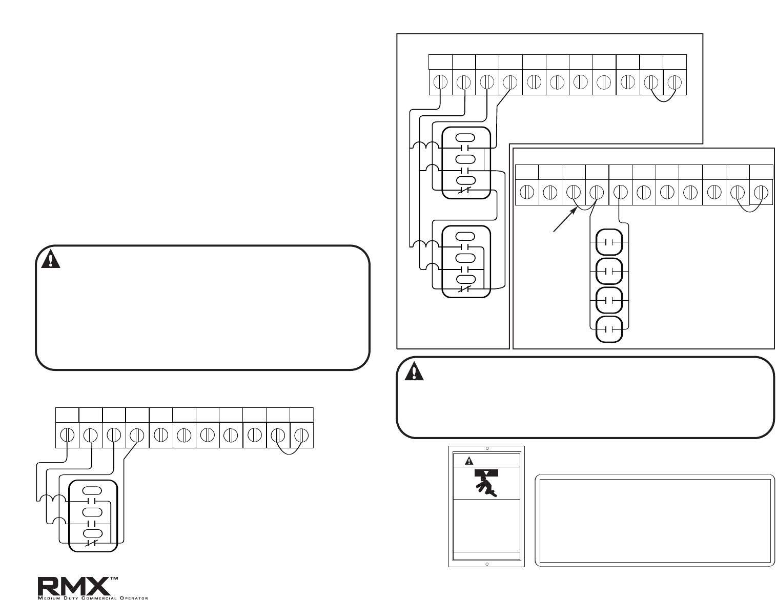
1) For a single 3 - button installation, make connections as
shown in Fig. 4.
2) F
or a multiple 3 - button installations, make connections as
shown in Fig. 5.
3)
F
or single button accessory controls, make connections as
shown in Fig. 6.
NOTE: If an External STOP button is NOT being installed, a jumper
wire must b
e installed b
etween the "STOP" AND "GND" terminals
as shown.
NOTE: Long Distance Relay Kit wiring is not required for long
distanc
e c
ontrol runs and should not be used.
Wall Control
OPEN CLOSE
STOP GND 1-BTN
N-O
SAFETY
N-O
SAFETY
ODC
STB
ODC
STB
EXT
INTLK
EXT
INTLK
OPEN
CLOSE
STOP
3-BUTTON
STATION
CONTROL SIGNAL TERMINAL STRIP
NOTE:
JUMPER BETWEEN STOP
AND GND TERMINALS
MUST BE REMOVED
OPEN CLOSE
STOP GND 1-BTN
N-O
SAFETY
N-O
SAFETY
ODC
STB
ODC
STB
EXT
INTLK
EXT
INTLK
OPEN
CLOSE
STOP
3-BUTTON
STATION
CONTROL SIGNAL TERMINAL STRIP
OPEN
CLOSE
STOP
3-BUTTON
STATION
NOTE:
JUMPER BETWEEN STOP
AND GND TERMINALS
MUST BE REMOVED
OPEN CLOSE
STOP GND 1-BTN
N-O
SAFETY
N-O
SAFETY
ODC
STB
ODC
STB
EXT
INTLK
EXT
INTLK
1-BTN
STATION
KEY
SWITCH
STATION
CARD
READER
OPEN/CLOSE
PULL
SWITCH
CONTROL SIGNAL TERMINAL STRIP
Figure 4
Figure 5
Figure 6
WARNING:
• Wall Control(s) must be located so that the door is
within sight of the user.
• Attach the Warning placard adjacent to the Wall
Control. Fig. 4A.
•
Attach the Caution label adjacent to the Wall Control.
Fig. 4B.
WARNING
Moving Door can cause
serious injury or death.
To prevent entrapment—
Do Not start door
downward unless doorway
is clear.
Install control switch and this sign so tha door is in sight
of the user. Do Not remove, cover or paint over this sign.
Entrapment
Warning
Placard
Figure 4A
NOTE:
JUMPER BETWEEN
STOP AND GND
TERMINALS
MUST BE INSTALLED.
CAUTION
This door is operated by a limited-duty operator.
To prevent the motor protector from tripping,
do not exceed 15 cycles of opening
and closing per hour.
NOT FOR RESIDENTIAL USE
Figure 4B
WARNING:
If momentary contact control is to be used, an external reversing device
such as a photocell system or sensing edge switch must be used. See
pages 5.6-5.7 for installation of entrapment protection devices.
www.overheaddoor.com 07/30/09
OPEN CLOSE
STOP GND 1-BTN
N-O
SAFETY
N-O
SAFETY
ODC
STB
ODC
STB
EXT
INTLK
EXT
INTLK
CONTROL SIGNAL TERMINAL STRIP
* REMOVE JUMPER WHEN
INSTALLING EXTERNAL INTERLOCK
*
Interlock Switches
Figure 7
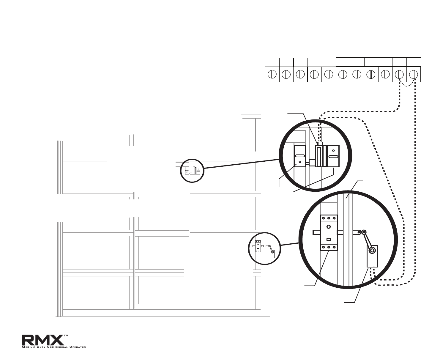
NOTE: If External Interlock is used,THE JUMPER WIRE BETWEEN THE
EXT INTLK TERMINALS MUST BE REMOVED.
1) Optional external interlock switches are required with some
Sectional or Rolling Steel Doors to prevent the door from
operating under certain conditions including the following:
• If the door is equipped with a functioning door lock, an
interlock switch must be installed to prevent electric
operation when the lock is engaged.
• If the door is equipped with a pedestrian pass-through door,
an interlock switch must be installed at the pass-through
door in order to prevent electrical operation when the
pass-through door is open.
SWITCH
075412-0000
(N.O.)
ANGLE
405964-0000
STANDARD
SLIDELOCK
TRACK
SWITCH
075396-0000
(N.C.)
Switches must be
set in the field.
5.5
Pass door interlock:
Should be open when
door is open.
Closed when door is
closed.
Side lock interlock:
Should be open when
door is locked.
Closed when door is
unlocked.
www.overheaddoor.com 07/30/09
5.6
Radio Control and Photocell Wiring
PWR
RAD GND
OPEN CLOSE
STOP GND 1-BTN
N-O
SAFETY
N-O
SAFETY
ODC
STB
ODC
STB
EXT
INTLK
EXT
INTLK
+
-
+
-
THRU-BEAM
PHOTOCELLS
CONTROL SIGNAL TERMINAL STRIP
RECEIVER TRANSMITTER
PWR
20-40 VDC @ 300mA
MAX CURRENT
EXTERNAL RADIO TERMINAL STRIP
CLASS 2 SUPPLY 0-40 VDC
OPEN CLOSE
STOP GND 1-BTN
N-O
SAFETY
N-O
SAFETY
ODC
STB
ODC
STB
EXT
INTLK
EXT
INTLK
SERIES II (STB) RESIDENTIAL SAFE-T-BEAMS
®
CONTROL SIGNAL TERMINAL STRIP
Figure 9
PWR
RAD GND
RELAY
GND
NOM
+24VDC
RADIO
PWR
20-40 VDC @ 300mA
MAX CURRENT
EXTERNAL RADIO TERMINAL STRIP
CLASS 2 SUPPLY 0-40 VDC
LOCATED
OUTSIDE
ELECTRIC
BOX
Figure 8
DOOR
Figure 10
Figure 11
CONNECT WIRES TO EITHER
TERMINAL.
(NOT POLARITY SENSITIVE)
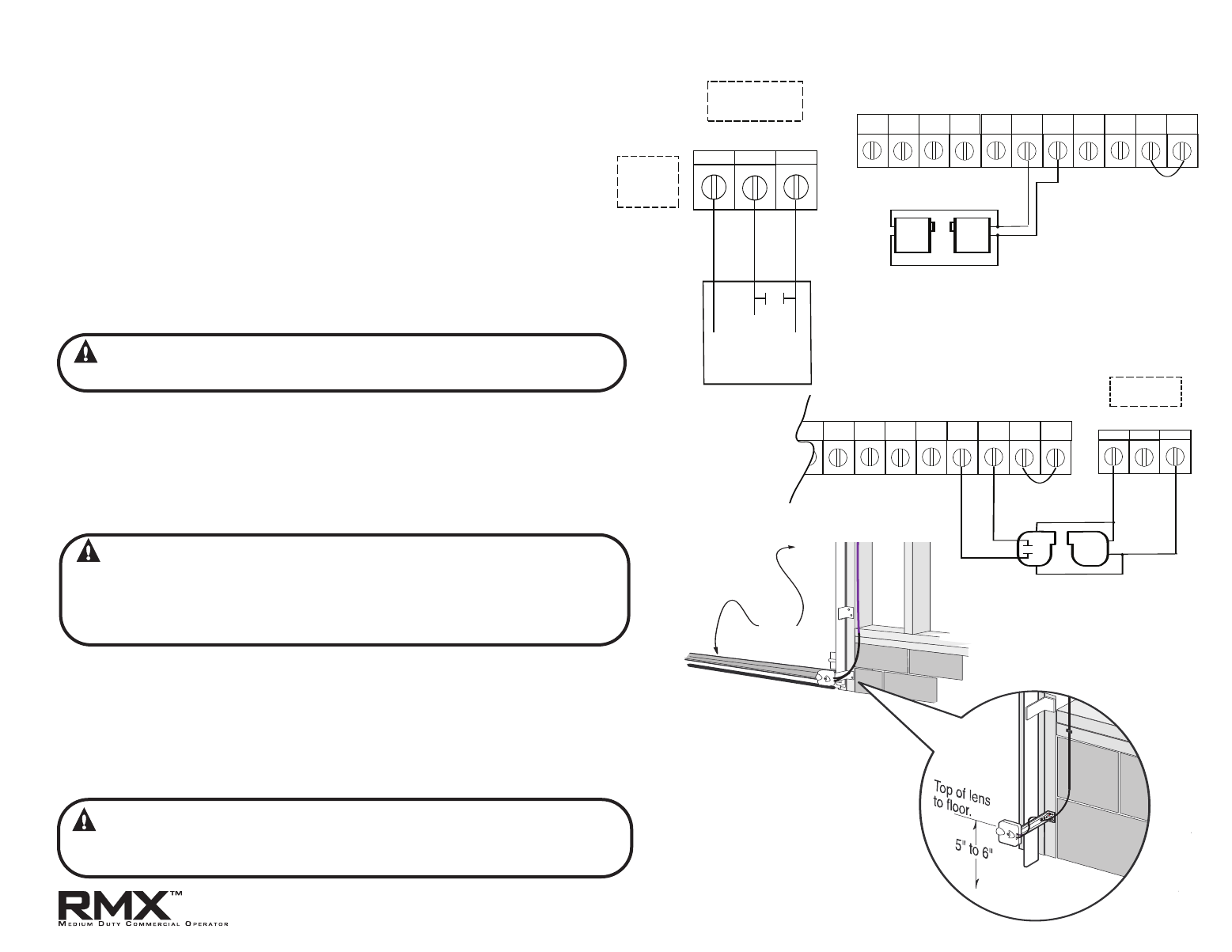
1) Monitored SERIES II (STB) photocells (P/N 35048R.S)
can be installed as shown in Fig. 9. Wiring to these photocells
can b
e connected to either terminal (they are not polarity
sensitive). ( Troubleshooting Section is Appendix D).
NOTE: Installer must enable STB in calibration mode. See page 6.5.
2) To Mount Photocells: (Kit includes detailed Instructions).
• Determine location for mounting. They do not need to be directly
adjacent to the door but must be somewhere along the wall where
there will be an unobstructed line between them. Fig 11.
• Screws provided for mounting on soft ma
terial (wood, drywall, etc.)
• They must extend out away from the wall sufficiently that no door
hardware breaks the plane of the photo-beam.
1) Nominal 24 Volt DC Commercial photocells with normally open
contacts can be connected as shown in Fig.10.
NOTE: PWR terminal supplies 20 – 40VDC. Photocells used must be
compatible with this voltage range.
NOTE: If no voltage is present at PWR Terminal, check fuse F-1 on Control board.
Series II Safe-T-Beam® Monitored Photocells
Radio Control Installation
1) For a 3-wire radio control installation, make connections as shown
in Fig. 8.
NOTE: PWR terminal supplies 20 – 40VDC. Radios used must be
compatible with this voltage range.
NOTE: If no voltage is present at PWR terminal, check fuse F1 on
control board.
Commercial Non-Monitored Photocells
WARNING:
Actuating the operator using constant contact on the
CLOSE button will override external reversing devices, including
photocells.
WARNING: Photocell systems provide entrapment protection
when mounted near the doorway in such a way that the lower
portion of an individual’s leg will break the photocell beam
during normal walking conditions. If an alternative location is
chosen it must be approved by the facility owner.
WARNING:
Actuating operator using constant contact on the CLOSE
button will override external reversing devices, including photocells.
www.overheaddoor.com 07/30/09
5.7
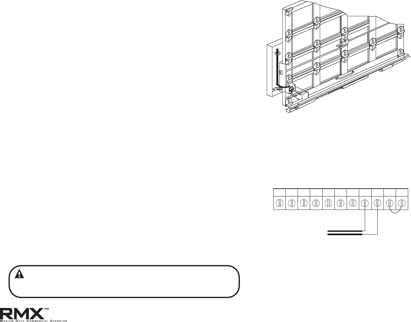
NOTE: Do not connect a 2-wire monitored sensing edge switch to
these terminals.
Figure 12 shows an example of a typical sensing edge installation. Left
hand side is shown but right hand is a mirror image of this.
1A) If wiring from sensing edge switch to operator is coiled cord
or 2 wire jacketed cord:
• Install junction box 12" above the center of the door
opening on same side as sensing switch.
• Secure one end of cord to junction box using a cable clamp.
1B) If connection is to be made through a take up reel cord:
• Install on same side as sensing edge switch and above door
opening and slightly to the side.
• Install junction box adjacent to take up reel and route the
stationary cord from the reel
to the box and secure with a
cable clamp.
2) Secure other end of cord (straight, coiled or reel) to sensing
edge switch enclosure using a cable clamp.
3) Connect wires of cord to sensing edge switch using wire nuts
or other suitable wire connectors.
4) Run a straight 2 wire cord from the junction box (Step 1) to
the operator electrical box.
• Secure using cable clamp on each end.
5) Join wires in cord from operator to wires in cord from switch
using wire nuts or other suitable wire connectors.
6) Connect to terminal strip using N-O Safety inputs. See Fig. 13.
7) Operate the door to make certain cord is free to travel and
does not become snared during
door opening or closing.
• Check sensing edge switch for proper operation.
Sensing Edge Switch Installation
OPEN CLOSE
STOP GND 1-BTN
N-O
SAFETY
N-O
SAFETY
ODC
STB
ODC
STB
EXT
INTLK
EXT
INTLK
SENSING EDGE SWITCH
CONTROL SIGNAL TERMINAL STRIP
Figure 13
Figure 12
WARNING:
Actuating the operator using constant contact on the
CLOSE button will override external reversing devices, including
sensing edges or reversing edges
www.overheaddoor.com 07/30/09
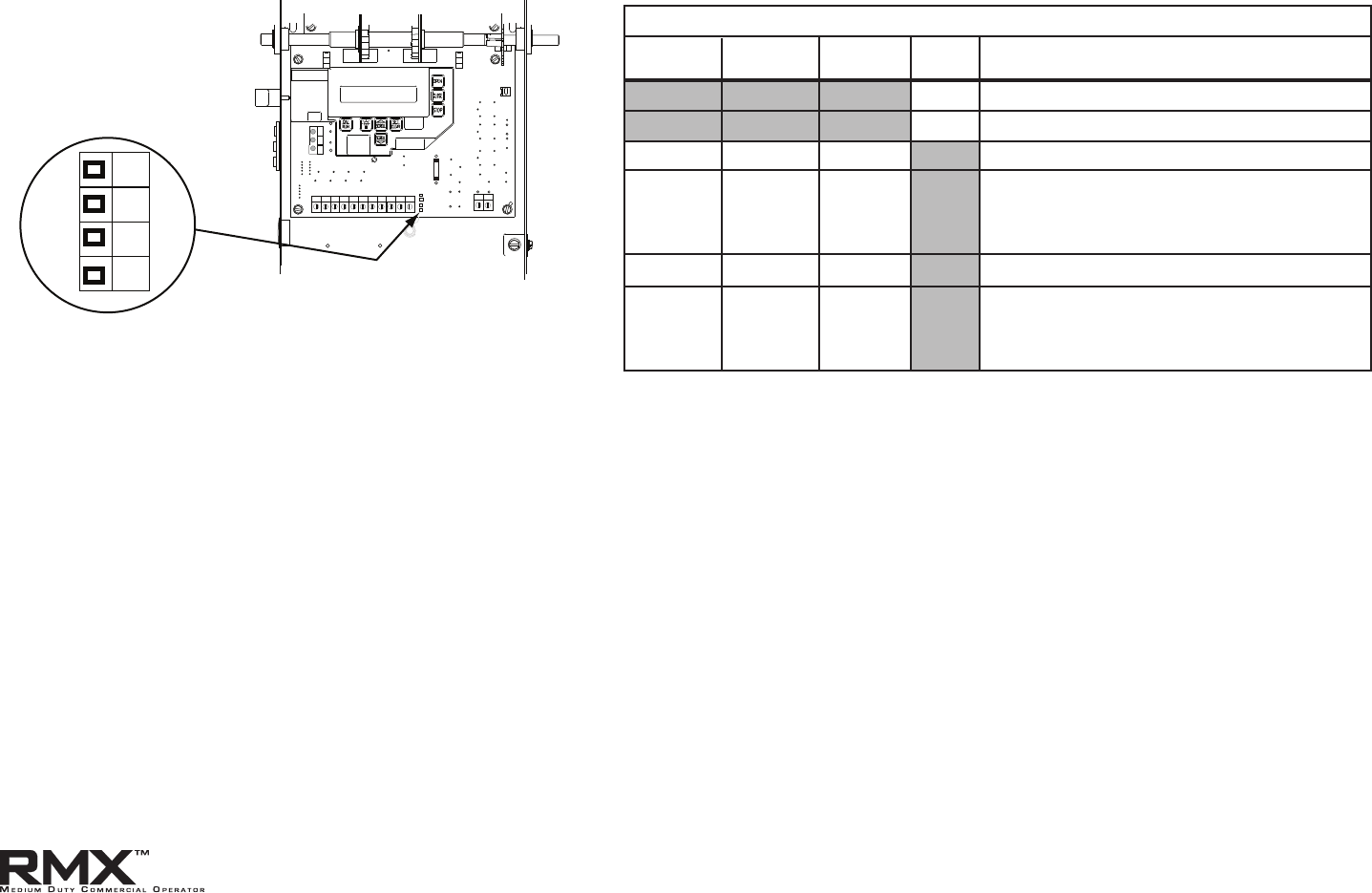
6.1
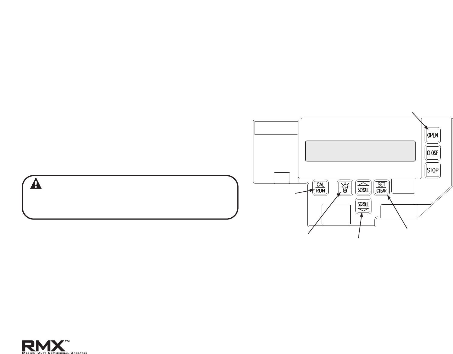
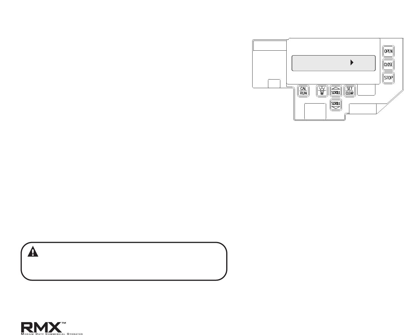
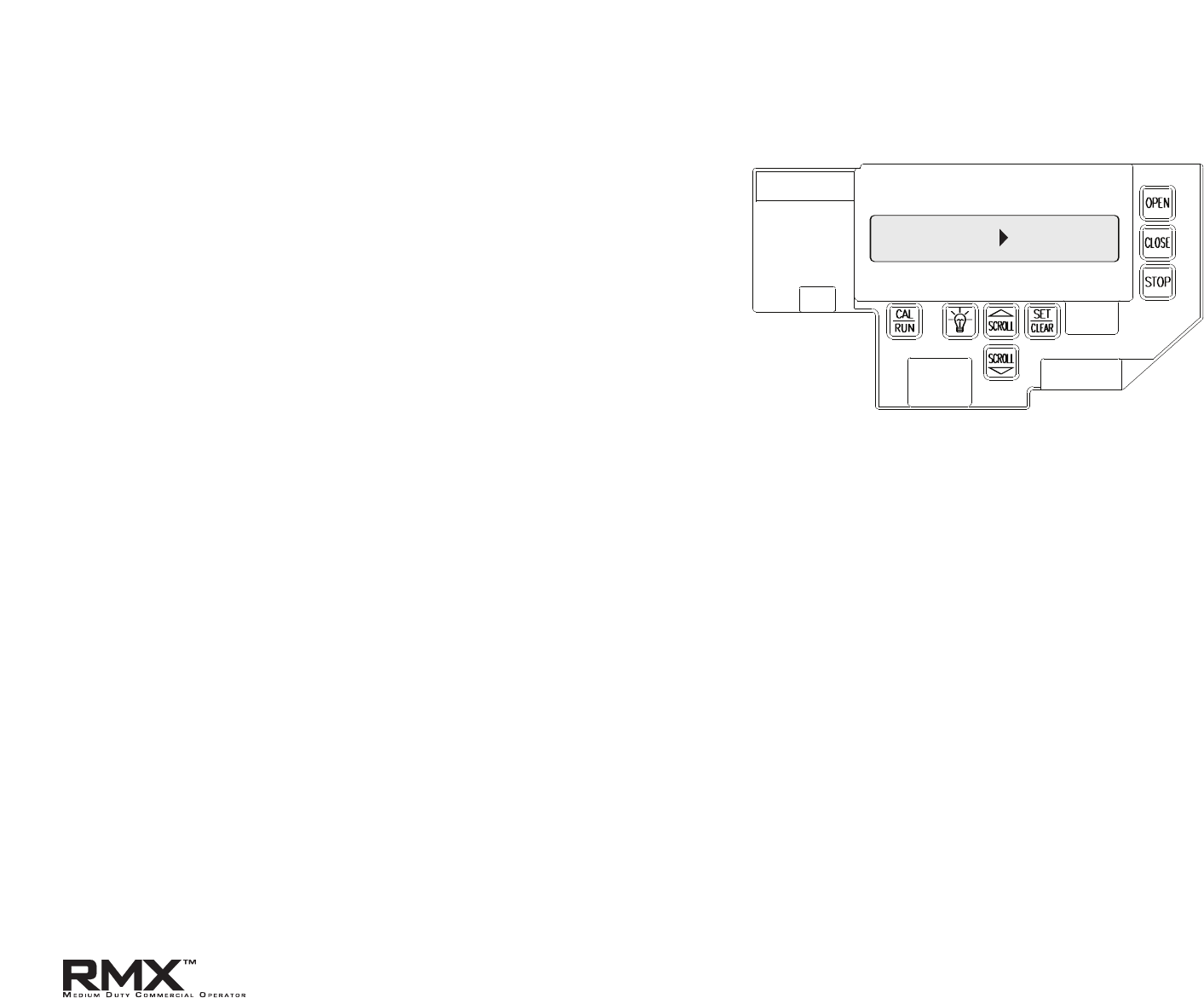
RMX™ Operators include a full function control panel including a liquid
cry
stal display (LCD), calibration keys and Open, Close and Stop keys for
on board operator control. See Fig. 1. The open, close and stop keys
func
tion as a 3-butt
on wall control. The Display will show current
operator conditions and calibration information. Due to limited
character space, some displays
will be abbreviated.
See Appendix C (pgs. 10.11-10.13) for full display descriptions.
RMX™ Operators include a non-volatile memory. The unit will
remember all calibration settings plus error code and run code logs, if
power is removed from unit.
NOTE: During Setup, refer to Caution Label for limited use (pictured on
page 5.4).
DANGER
After power is supplied to the operator, Do Not make contact
with components inside the control panel except for the
Keypad Keys. Fig. 1.
Control Operating Modes
RMX™ Operator control boards operate in two modes: Run Mode and
C
alibr
ation Mode. The control board should normally operate in the
Run Mode. The operator is calibrated in Calibration Mode.
With the opera
tor standing idle:
PRESS CAL/RUN TO TOGGLE BETWEEN OPERATING MODES.
• The first display in calibration mode is "open mode > ***”
(*** = curr
en
t operating mode).
• The display in run mode will be one of the condition codes listed
in Appendix C.
NOTE:The CAL/RUN key will not toggle between operator modes while
the opera
t
or is running.
Section 6: Operator Setup Procedure
Control Panel
LCD DISPLAY
Figure 1
Calibration &
R
un Mode
Toggle Key.
Display
Backlighting
Toggle Key.
Scroll Keys, used in
Calibration Mode.
Set/Clear Key,
used to reset
and adjust
calibration
settings.
Operation Keys,
operates unit
like a 3-button
wall station.
www.overheaddoor.com 07/30/09
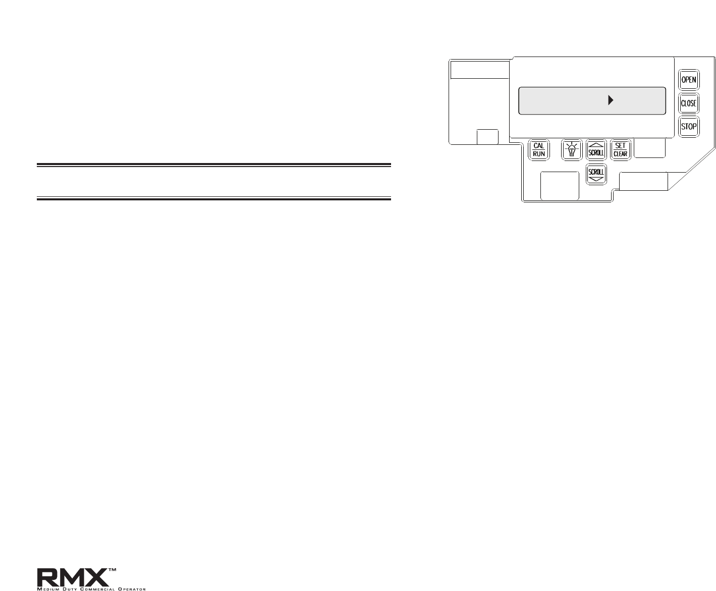
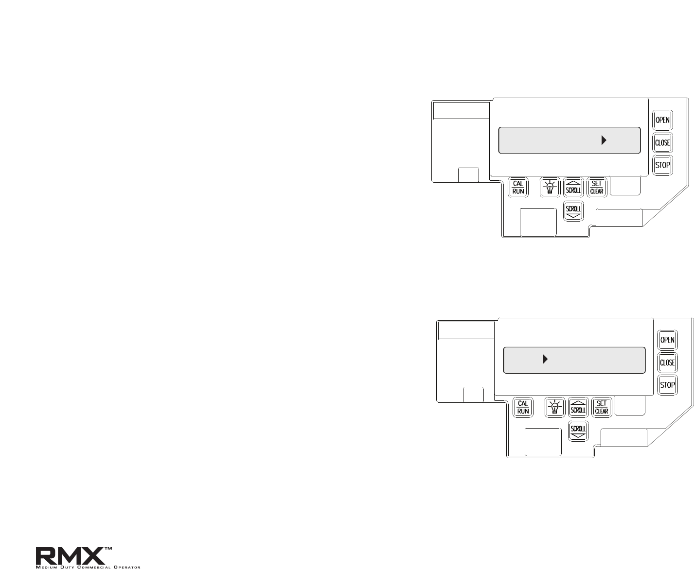
Setting Constant Contact
IDLE DOWN LIMIT
OPEN MODE C-STP
CLOSE MODE MOM
Figure 2
Figure 3
Figure 4
Door closed -
operator
standing by
CLOSE MODE C-STP
Figure 5
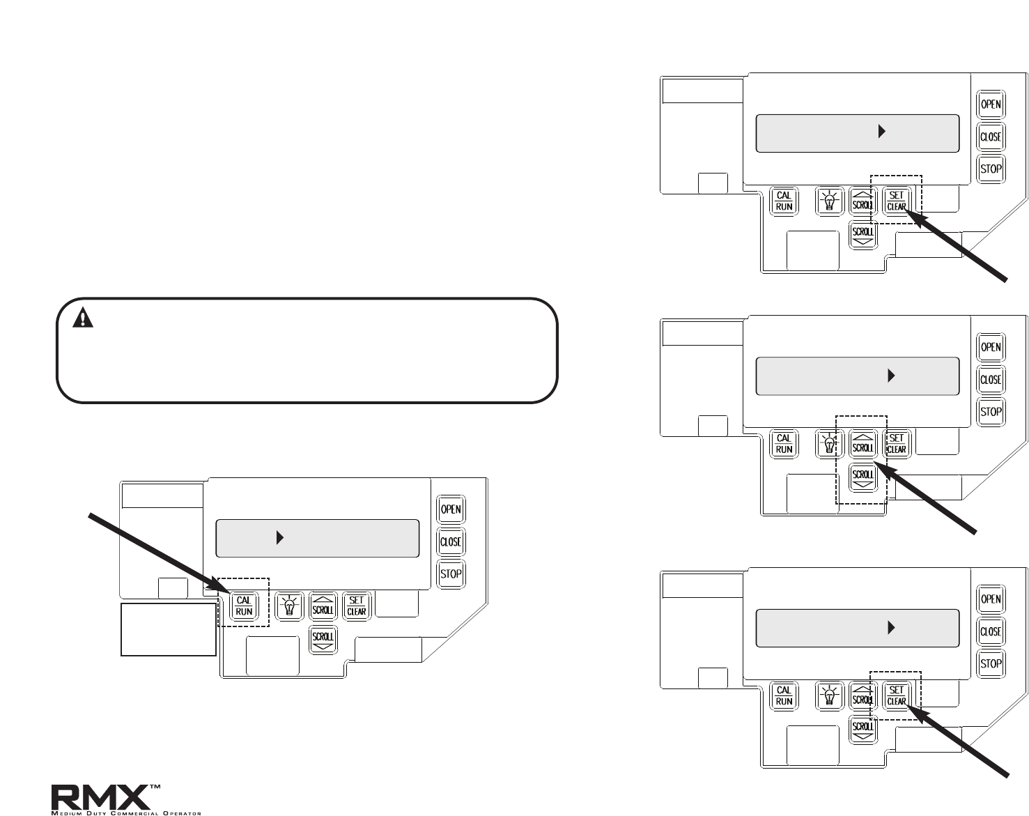
RMX™ Operators are shipped from the factory with both open and close
operating modes set to constant contact – stop (C – STP) If your unit is set
to Momentary Contact (MOM) Open and/or CLOSE, reset the
operating modes by taking the following steps:
1) Press CAL/RUN to enter calibration mode. Fig. 2.
2)
P
ress SET/CLEAR until display reads “OPEN MODE
>
C-STP.” Fig. 3.
3) P
ress SCROLL (DN) until display reads “CLOSE MODE.” Fig. 4.
4) P
ress SET/CLEAR until display reads “CLOSE MODE
>
C-STP.”
Fig. 5.
5) P
r
ess CAL/RUN to return to run mode.
6.2
WARNING:
If an external reversing device is not used, then the operator must
be used with only a Constant Contact Control. Verify closemode
is set to “C-STP” and NOT “C-REV” or “MOM” before continuing.
www.overheaddoor.com 07/30/09
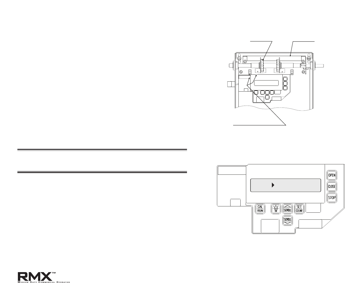
1) Engage door to Operator.
NOTE: Verify open and close operating modes are set to constant
con
tact – Stop (C-STP). See page 6.2 for details.
2) Press CAL/RUN until operator is in run mode.
3) Press and hold OPEN Key on Control Panel. Run door to
desired open position, release OPEN Key.
4) Push LIMIT LOCKING BAR away from Limit Sensors and
turn Open Limit Travel Nut until travel nut arrow and open limit
sensor arrow are aligned and the display reads “IDLE
>
UP LIMIT.”
5) R
elease the LIMIT L
OCKING BAR and make sure bar seats
completely into both Travel Nuts. Fig. 6.
6)
P
ress and hold CLOSE key on Control Panel. Run door to
within 2" above floor, release Close button.
NOTE: If the operator stops while trying to set limits and the display
reads “GDO shut
down>MRT / Hit key to r
eset,” see page 6.6 "Resetting
Max Run Timers".
7) Push LIMIT LOCKING BAR away from Limit Sensors and
turn Close Limit Travel Nut until travel nut arrow and close limit
sensor arrow are aligned and the display reads “IDLE
>
DOWN
LIMIT.” Fig. 7.
8)
R
un door fully Open and Closed with Open & Close Keys on
control panel and make final adjustments as necessary to make
sure that door opens fully and closes no more than 2" above
the floor.
6.3
Setting Limit Travel
IDLE DOWN LIMIT
UP LIMIT TRAVEL NUT
LIMIT SENSOR ALIGNMENT ARROWS
LIMIT LOCKING BAR
Figure 6
Figure 7
www.overheaddoor.com 07/30/09
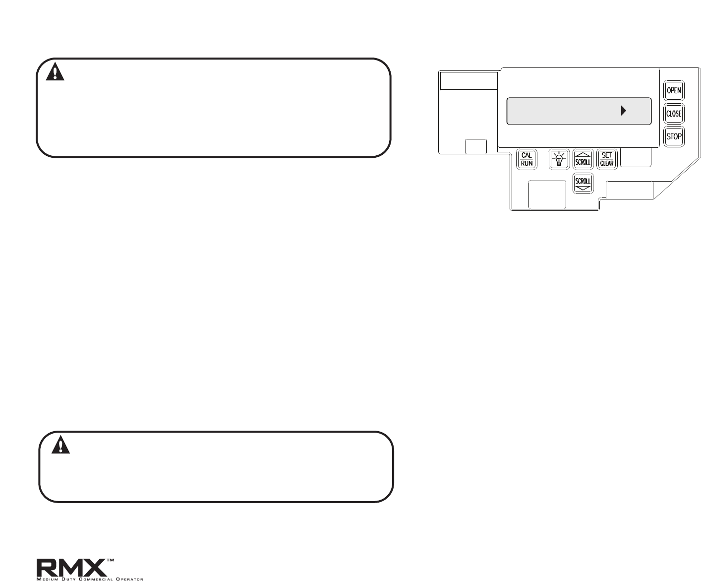
WARNING: The Limit Overrun function will override external
reversing devices, including photocells and sensing edges or
reversing edges. Therefore, any externally connected devices
will be disabled during that portion of the door travel controlled
by the Limit Overrun function.
The Down Limit Overrun function should be used to close the
door no more than the final 2".
A) The Limit Overrun setting is a matter of trial and error.The goal is
to adjust the Limit O
verrun until an appropriate seal is obtained
between the bottom edge of the door and the floor.
B) The Limit Overrun setting can be varied between 0 and 9.
0-
disables the Limit Overrun so that the door stops at the down
limit switch setting.
9- causes the greatest amount of door travel beyond the limit
switch setting. Door should close gently with
light tension on door
cables, or minimal stacking on rolling steel slats.
1) Press CAL-RUN to enter calibration mode
2) Press scroll (DN) until the display reads “LIMIT OVERRUN
>
(0-9).”
Fig.8.
3)
P
ress SET/RUN until the display reads the desired value.
4) Press the OPEN key to open the door a few feet, then release
5) Press the CLOSE key to close the door and hold until the
operator stops.
6) Check the door seal and repeat steps 3-5 until the appropriate
seal is obtained between the door and the floor.
CAUTION: If proper seal cannot be obtained at a setting of 9,
Reset the Limit Overrun back to 0 and reset the Down Limit
position as described on pg. 6.3..Then adjust the Limit Overrun
as instructed above.
7) Press CAL-RUN to return to Run mode.
6.4
Setting Limit Overrun
LIMIT OVERRUN 0
Figure 8
www.overheaddoor.com 07/30/09

NOTE:The RMX™ Operator can use monitored SERIES II Photocells
(STB). If your application requires these photocells, they must be activat-
ed in calibration mode.
1) Press CAL/RUN to enter calibration mode.
2) Press scroll (DN) until display reads "ODC STB
>
"
3) P
ress SET/CLEAR) un
til display reads "ODC STB
>
ON"
• The
“STB ENAB” LED on the control board should light.
4) Press CAL/RUN to return to run mode.
NOTES
A) To turn series II photoc
ells off,
repeat process until display reads
"ODC STB
>
OFF." Fig. 9.
B) Installation of S
eries II monitored photocells (STB) does NOT
make the RMX™ unit legal for r
esidential installation. Overhead
Door does NOT recommend the installation of the RMX™ unit in
residentially zoned construction.
6.5
Using Series II Safe-T-Beam
®
(STB)
Monitored Photocells
ODC STB OFF
Figure 9
WARNING:
Photocell systems provide entrapment protection when
mounted near the doorway in such a way that the lower
portion of an individual’s leg will break the photocell beam
during normal walking conditions. If an alternative location is
chosen it must be approved by the facility owner.
www.overheaddoor.com 07/30/09
6.6
The RMX™ Operator will automatically set its maximum run timers
(MRT) when the unit is r
un from limit to limit in the run mode.The Max
Run Timer is a feature that prevents the unit from running continuously
in the event of a slipping clutch, etc.
NOTE:The MRT’s are set to the time required to run from one limit to
the other
, plus 5 sec
onds (nominal). When the MRT is exceeded, the
operator stops and may reverse (only on a close attempt with trolley
unit). The operator will not respond to any command until it is reset by
pressing one of the calibration keys or by cycling power to the unit.
Resetting the Max Run Timers
The Maximum Run timers can be reset to their default values using this
procedure:
1) Press CAL/RUN to enter calibration mode.
2) Press Scroll (DN) until display reads “MAX RUN TMR
>
SET.”
3)
Press SET/CLEAR until display reads “MAX RUN TMR
>
CLEAR.”
FIG. 10.
4)
Pr
ess CAL/RUN to return to run mode.
NOTE:The Max R
un Timers must be reset each and every time the
trav
el limits are adjusted.
CAUTION:
The Mid-Stop feature must be turned off to properly set the
maximum run timers.
Max Run Timer
MAX RUN TMR CLR
Figure 10
www.overheaddoor.com 07/30/09
The RMX™ Operator includes a programmable Mid-Stop.This feature
allows the operator stop at a user selectable point when opening. It is
used when operating very tall doors that only open to their full height
occasionally. The Mid-Stop does not effect the operator when closing.
1) To operate door to full open position from mid-stop, press open
button again.
NOTE: Setting of the MID-STOP should only be performed AFTER Travel
Limit and M
ax Run Timer settings have been made.
To set the Mid-Stop:
1)
Pr
ess CAL/RUN to enter calibration mode.
2) Press the CLOSE key to close the door to the down limit.
3) Press SCROLL (DN) until the display reads “MID-STOP
>
CLEAR.”
Fig. 11.
NOTE: If the display reads MID-STOP
>
SET at this point, first clear the
MID-ST
OP as describ
ed below then repeat steps 1-3 and continue.
4) Press the OPEN key to open the door and release the key
when the door is at the desired Mid-Stop height.
5) Press the SET/CLEAR until the display reads “MID-STOP
>
SET.”
6) Press C
AL/RUN t
o return to run mode.
To clear the Mid-Sto
p:
1) P
ress CAL/RUN to enter calibration mode.
2) Press SCROLL (DN) until the display reads MID-STOP
>
SET.
3) Press SET/CLEAR until the display r
eads MID-STOP
>
CLR
4) Press CAL/RUN to return to run mode.
6.7
Setting the Mid-Stop
MID-STOP CLR
Figure 11
www.overheaddoor.com 07/30/09
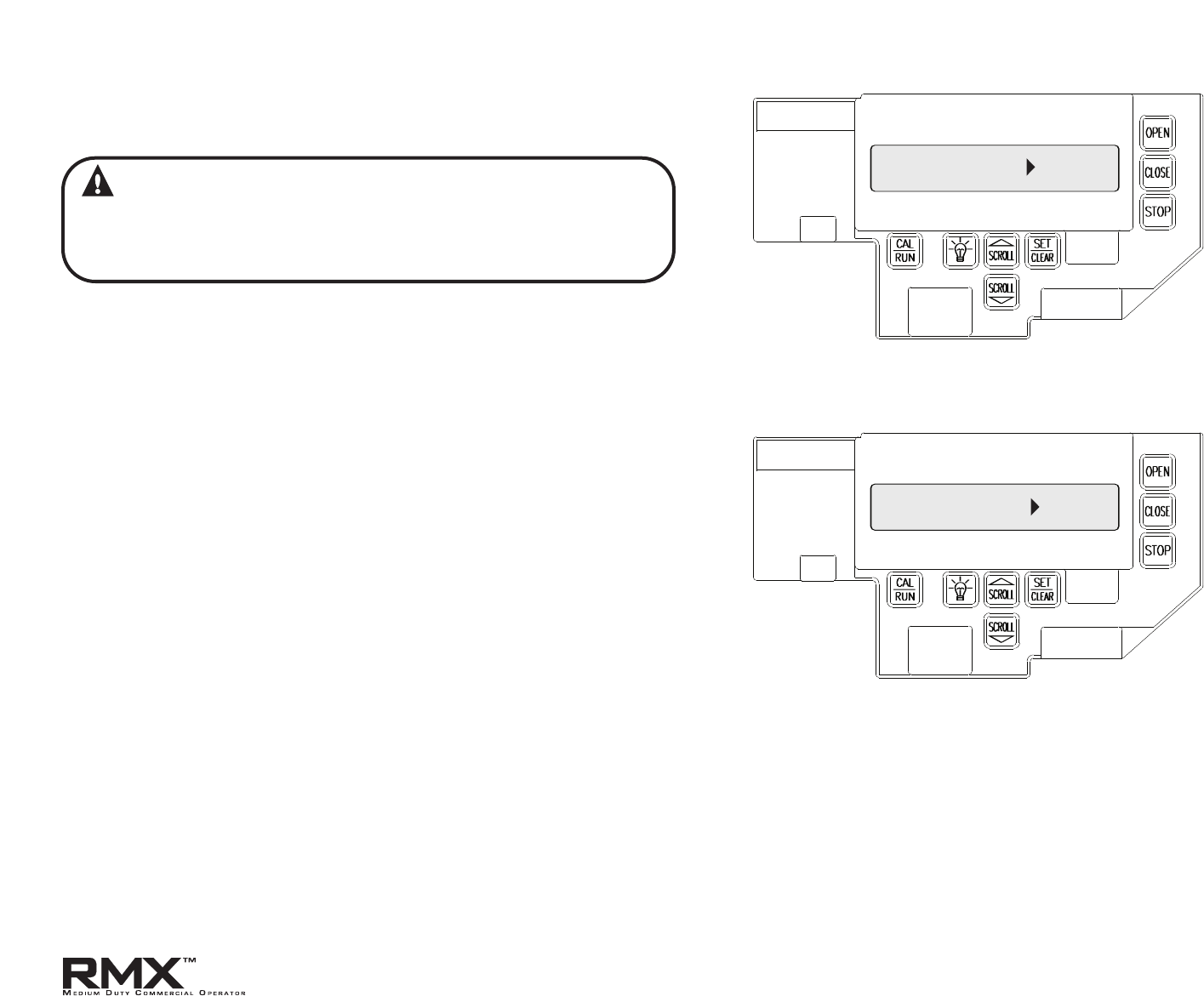
NOTE: Once the travel limit and safety modes have been set, the OPEN and
CLOSE modes may be set for Momentary Contact if desired.
NOTE:The radio control input will not operate when the open or close
mode is set in the Constant Contact mode. Operating modes affect all
control inputs and keys.
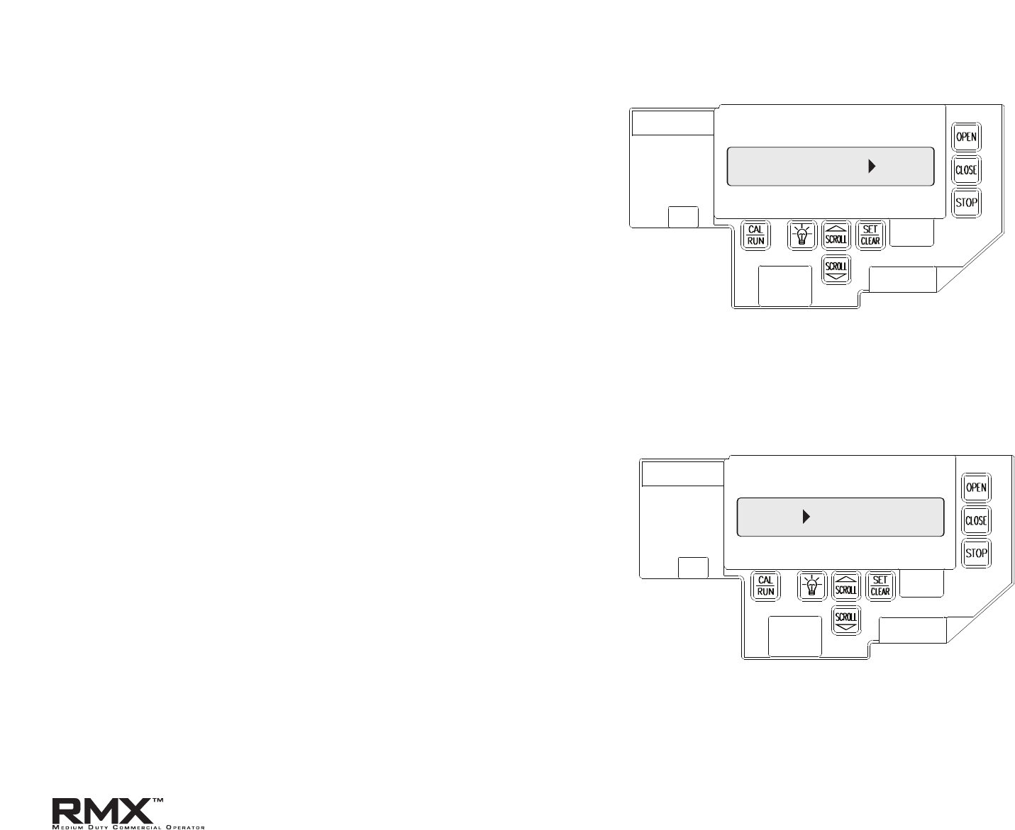
To set the OPEN mode: Fig. 12.
1) Pr
ess CAL/RUN to enter the calibration mode.
2) Press SCROLL (DN) or (UP) until display reads “OPEN MODE
>
.”
• This displa
ys current setting.
3) Press SET/CLEAR until the display reads the desired operating mode:
• C-STP = Constant contact is required to open door. Door will
stop if button or key is released before operator reaches its limit.
• MOM = Momentary contact will cause door to open to limit.
4) Press CAL/RUN to return to run mode.
To set the CLOSE mode: Fig. 13.
1) Press CAL/RUN to enter the calibration mode.
2) Press SCROLL (DN) or (UP) until display reads “CLOSE MODE
>
“.
This displays current setting.
3)
Press SET/CLEAR until the display reads the desired operating mode:
• C-STP = Constant contact is required to close door. Door will
stop if button or key is released before operator reaches its
limit.
• C-REV = Constant contact is required to close the door. Door
will reverse automatically if stop button or key is released
before door reaches down limit.
• MOM = Momentary contact will cause door to close to limit.
4) Press CAL/RUN to return to run mode.
6.8
Changing Open and Close Modes
OPEN MODE MOM
CLOSE MODE MOM
Figure 12
Figure 13
WARNING
If momentary contact control is to be used, an external
reversing device such as a photocell system or sensing edge
switch must be used.
www.overheaddoor.com 07/30/09
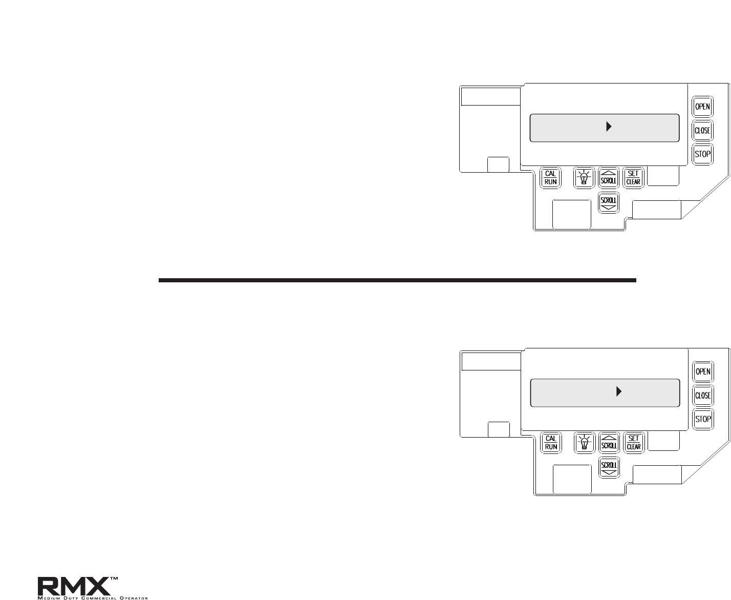
RMX™ operators include a built-in cycle counter that store the count with
or without power to the operator.
To view the Cycle Count:
1)
P
ress CAL/RUN to enter calibration mode.
2) Press SCROLL (DN) or (UP) until display reads “CYCLES
>
.”
T
his will displa
y current cycle count.
3) Press CAL/RUN to return to run mode.
7.1
Section 7: Special Operator Features
Operator Cycle Count Fig. 1
RMX™ operators can display the version number of the firmware used in
the on-board micro-controller.
To view this version number:
1) Press CAL/RUN to enter calibration mo
de
.
2) Press SCROLL (DN) or (UP) until the display reads “FIRMWARE
>
.”
“
T
his will display the current firmware version number.
3) Press CAL/RUN to return to run mode.
Circuit Board Firmware Version Fig. 2
CYCLES 1
FIRMWARE 4.00.1
Figure 1
Figure 2
www.overheaddoor.com 07/30/09
RMX™ operators are available for use in jackshaft or trolley configurations.
The same control board is used for either configuration, however the
control board must be set for the appropriate GDO configuration. A board
set for trolley mode will not work in a jackshaft operator and vice-versa.
NOTE:The GDO type is factory set. The installer should not have to set
this f
ea
ture. However, if the GDO type is inadvertently changed, or if a
board needs to be replaced in the field, follow these instructions to set
GDO type.
1) Press CAL/RUN to enter calibration mode.
2) Press SCROLL (DN) or (UP) until display reads “GDO TYPE
>
.”
This will display the current GDO t
yp
e.
3) Press SET/CLEAR until display indicates correct GDO type
( J-SHAFT or TROLLEY)
4) Press CAL/RUN to return to run mode.
7.2
Operator Type Fig. 3
GDO TYPE J-SHAFT
Figure 3
www.overheaddoor.com 07/30/09
8.1
Section 8: Troubleshooting
RMX™ operators display their status on the integral display. Each time the
operator runs, stops, reverses or refuses to run, the display will indicate why
the action did, or did not take place.
Once an error code has been generated, the RMX™ operator will continue
to display the error code while the operator is not running.This error code
can be cleared by pressing the STOP button or STOP key on the keypad.The
error code will automatically clear when the operator stops at the down
limit. Error codes will continue to be stored in the RMX™ operator’s Error
Code Memory after they have been cleared from the display in the
Run Mode.
Display Operation in Run Mode
To aid in troubleshooting problems, RMX™ operators include an error code
memory that stores the last 10 error events.These codes are stored with or
without power.The last error code detected is also displayed on the LCD
until the stop button or key is pressed or the operator stops at the down
limit.
The error code memory stores the last 10 error codes in sequence. Once 10
codes are stored, the oldest code is erased to make room for the newest
code.These codes are displayed in calibration mode.The display will flash
the number of the error code and the 2-digit error code followed by a
description of the error code. Fig. 1 & 2.
Error Codes
ERROR CODE 1 41
Figure 1
REV ONE BUTTON
Figure 2
www.overheaddoor.com 07/30/09
8.2
To view the error code memory: (Fig. 1 & 2)
1) Pr
ess CAL/RUN to enter calibration mode.
2) Press SCROLL (UP) or (DN) until display reads
“ERROR CODE 1
>
”.
•
The display will begin flashing the error code number and
2-digit error code followed by its description.
• Reminder: Error code number 1 is the latest code generated.
3) Press SET/CLEAR. The display will now read “ERROR CODE 2
>
.”
(
This is the er
ror code which was generated before error code 1.)
4) Repeat step 3 until all 10 error codes have been displayed or
move on to step 5 when ready.
5) Press CAL/RUN to return to run mode.
NOTE: For all error codes see Appendix C, Sections 10.12 - 10.13.
Error Codes (cont’)
RMX™ operators also include a run c
ode memory that stores the last 10 run
events.These codes are stored with or without power. Each time the
operator runs or stops, it generates a code that it stores in this memory
(Why the operator ran or stopped). Used together with the error code
memory, it becomes a powerful troubleshooting aid.
The run code memory stores the last 10 error codes in sequence. Once 10
codes are stored, the oldest code is erased to make room for the newest
code.These codes are displayed in calibration mode.The display will flash
the number of the run code and the 2-digit run code followed by a
description of the run code. Fig
. 3 & 4.
Run Codes
RUN CODE 1 3C
Figure 3
HALT DOWN LIMIT
Figure 4
www.overheaddoor.com 07/30/09
To view the run code memory: (Fig. 3 & 4)
1) Press CAL/RUN to enter calibration mode.
2) Press SCROLL (UP) or (DN) until display reads “RUN CODE 1
>
.”
•
The display will begin flashing the run code number and code
followed by its description.
• Remember: run code number 1 is the latest code generated.
3) Press SET/CLEAR.The display will now read “RUN CODE 2
>
.”
(
This is the run code which was generated before run code 1.)
4) Repeat step 3 until all 10 run codes have been displayed or
move on to step 5 when ready.
5) Press CAL/RUN to return to run mode.
NOTE: For all run c
odes see Appendix C, Section 10.11.
Run Codes (cont’)
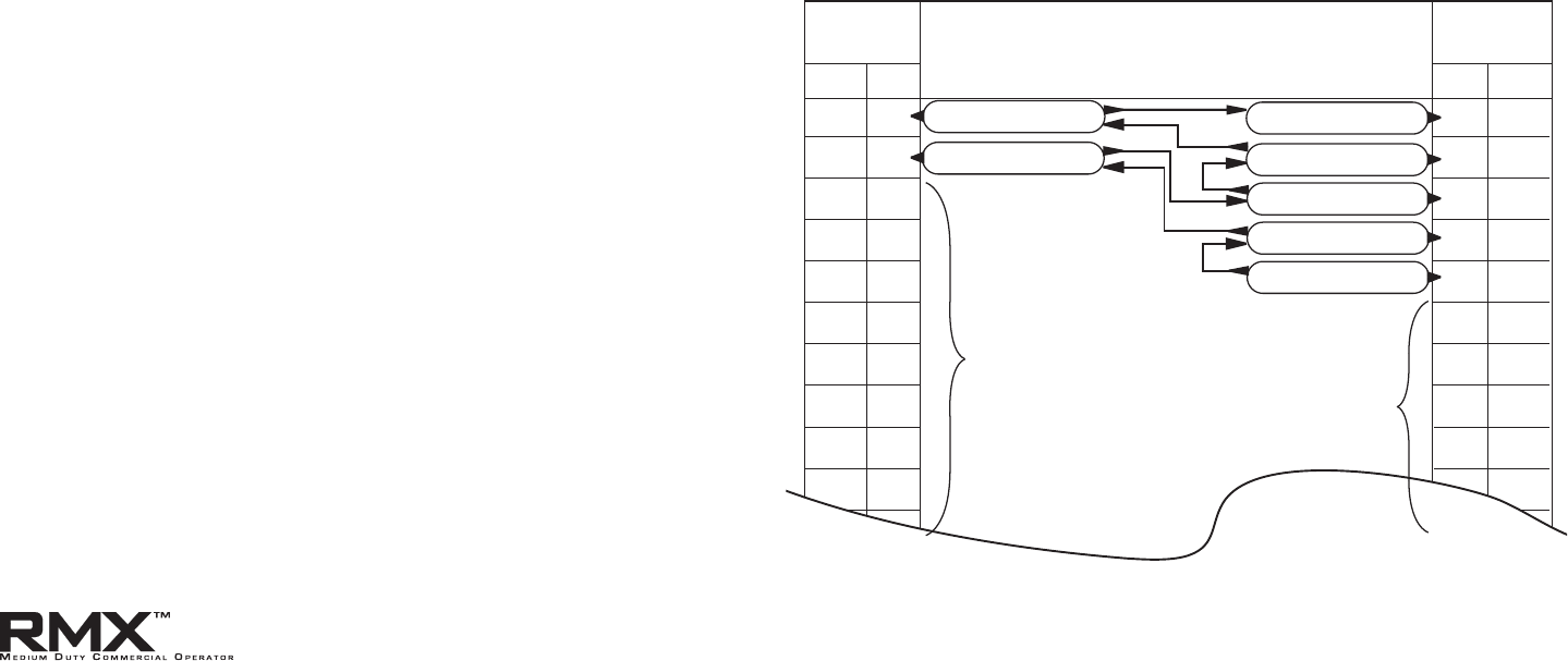
TROUBLESHOOTING EXAMPLE USING RUN AND ERROR CODE
MEMORIES.
Fig. 5
1. In Calibration Mode, display and write down each Run Code
and Error Code stored in memory.
2. List as shown below.
3. R
efer to Appendix C to interpret the codes.
In this example, the operator was opened using the OPEN key on
the keypad and stopped at the up limit. The OPEN wall button
was then activated, causing the “6D” code to be generated since
the operator could not open when it is already at the up limit.
The CLOSE wall button was then activated, causing the operator
to close. While closing, the Normally-Open (N-O) Safety Input
was activated, causing the operator to stop and then reverse,
stopping at the up limit.
ERROR
CODES
RUN
CODES
1
2
3
4
5
6
7
8
9
10
1
2
3
4
5
6
7
8
9
10
11
45
6D
00
00
00
00
00
00
00
00
00
00
00
00
00
00
00
00
00
00
00
00
00
3D
35
20
3D
14
REVERSED DUE TO ACTIVE
N-O SAFETY INPUT
WOULD NOT OPEN —
ALREADY AT UP LIMIT
STOPPED AT UP LIMIT
STOPPED DUE TO ACTIVE
N-O SAFETY INPUT
CLOSED FROM
CLOSE WALL BUTTON
STOPPED AT UP LIMIT
OPENED FROM
OPEN KEY ACTIVATION
RMX STORES “00” CODES IN UNUSED RUN AND ERROR
CODE MEMORY LOCATIONS AT THE TIME OF
MANUFACTURE. AS ERROR OR RUN CODES ARE
RECORDED, THE “00” CODES ARE REPLACED WITH VALID CODES
NUMBER
CODE
NUMBER
CODE
Figure 5
8.3
www.overheaddoor.com 07/30/09
8.4
RMX™ operators include a self-diagnostic circuit board using
troubleshooting LED indicators to signal the technician of
a problem.
LED Indicators Fig. 6
Figure 6
HOIST
INTERLOCK
TROUBLESHOOTING LED’s
EXTERNAL
INTERLOCK
+ 24 VOLTS
DC
STB
ENABLE
INDICATION
OFF
OFF
OFF OFF
OFF OFF OFF
ON
ON ON ON
ON ON
ON
NORMAL OPERATING CONDITION
STB DISABLED
STB ENABLED
HOIST INTERLOCK SWITCH OPEN:
1) HOIST RELEASE NEEDS RESET.
2) HOIST INTERLOCK CONNECTOR NOT PLUGGED IN.
3) HOIST INTERLOCK DEFECTIVE.
POWER SUPPLY PROBLEM:
1) CHECK AC POWER SUPPLY.
2) CHECK MAIN POWER FUSE.
3) CHECK SECONDARY FUSE (2A).
EXTERNAL INTERLOCK OPEN
www.overheaddoor.com 07/30/09
OPEN CLOSE
STOP GND 1-BTN
N/O
SAFETY
N/O
SAFETY
ODC
STB
ODC
STB
EXT
INTLK
EXT
INTLK
24VAC RADIO
GND
L1
N
STB
ENAB
+ 24
VAC
EXT
INTLK
HOIST
INTLK
TROUBLESHOOTING
LED'S
STB
ENAB
+ 24
VAC
EXT
INTLK
HOIST
INTLK
DETAIL
9.1
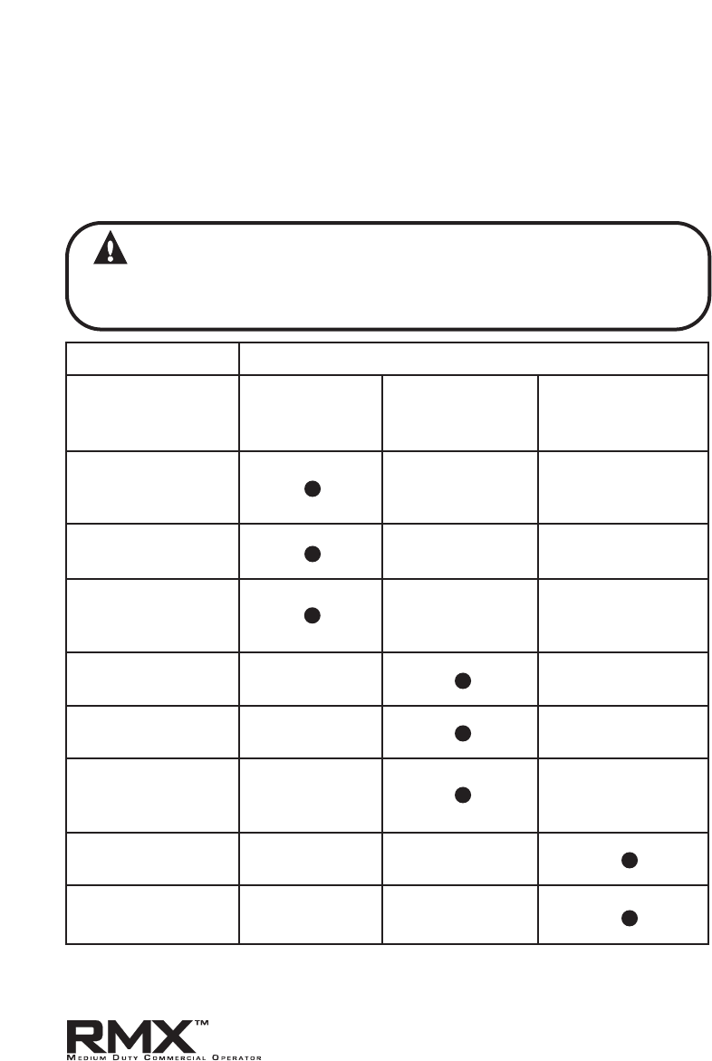
Section 9: Service and Maintenance
Maintenance Schedule
The following table provides a schedule of recommended Service and
Maintenance items to be completed by a trained service representative.
CAUTION
Failure to perform the recommended Service & Maintenance
may result in premature failure of the operator.
SERVICE ITEM SERVICE INTERVAL (FREQUENCY)
EVERY 6 MO. EVERY 12 MO. EVERY 36 MO.
OR OR OR
5,000 CYCLES 10,000 CYCLES 30,000 CYCLES
MANUAL
OPERATION OF
DOOR
DRIVE CHAIN
TENSION
*
PHOTOCELL/
SENSING EDGE
OPERATION
CLUTCH
ADJUSTMENT
BRAKE
ADJUSTMENT
CHECK FOR LOSE
OR MISSING
HARDWARE
CHECK LIMIT
POSITION
GEAR TRAIN
WEAR
*
ALL EXTERNAL REVERSING DEVICES SHOULD BE CHECKED MONTH.
www.overheaddoor.com 07/30/09
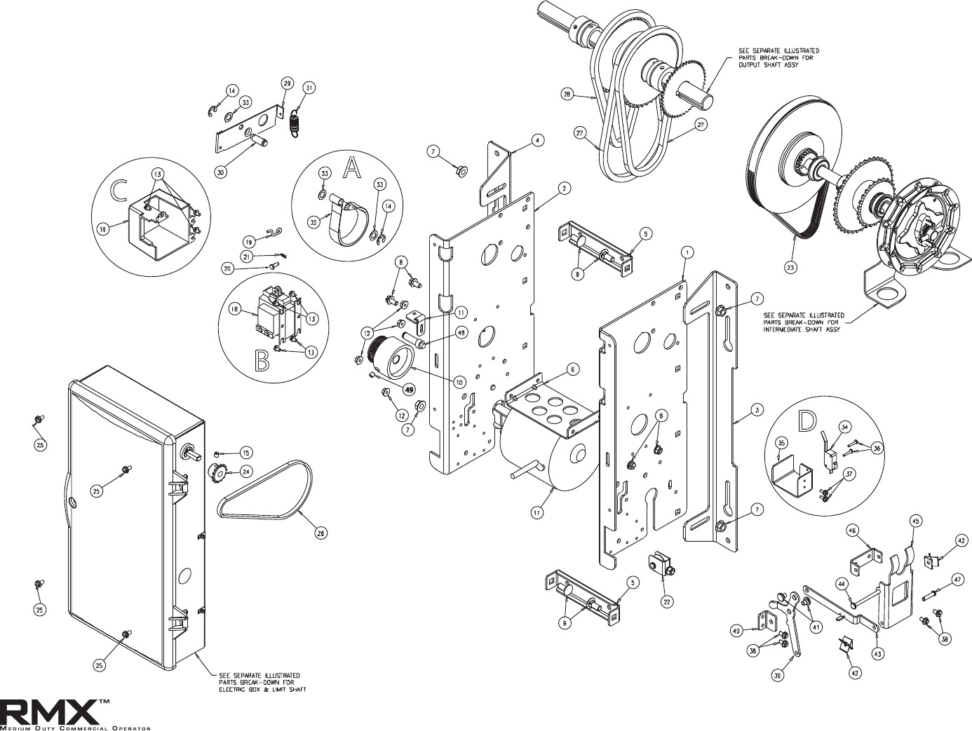
10.1
Section 10: Appendix A
Operator Exploded View (Hoist)
www.overheaddoor.com 07/30/09
49

10.2
Operator Parts List (Hoist)
Item Part Number Kit Includes Description Qty
A 110956-0001 Kit, Brake Band
110450.0001 Brake Band, MX 1
080415.0016 Ring, RTNG, EXT, "E", STL, 5/16"S 1
106124.0007 WSHR, NYL .375" ID X .625" OD 2
110960.0001 Instructions (not shown) 1
B 110953.0001 Solenoid Kit 120V
110847.0001 Solenoid 120V 1
086575.0604 Screw 4
110954.0001 Solenoid Kit 240V
110847.0002 Solenoid 240V 1
086575.0604 Screw 4
C 110952.0001 Solenoid Cover Kit
110549.0001 Cover 1
086575.0604 Screw 3
D 110975-0001 Interlock Switch Kit
108190.0001 Switch 1
110805.0001 Bracket 1
24173F04 Screw 2
24173B04 Screw 2
110976.0001 Instructions 1
1 110421.0002 Enclosure, Right Side 1
2 110421.0001 Enclosure, Left Side 1
3 110425.0002 Bracket, Mounting, Right 1
4 110425.0001 Bracket, Mounting, Left 1
5 110803.0001 Brace, Support 2
6 110804.0001 Bracket, Support 1
7 24121C05 Nut, 5/16-18 HX SERR FLG 4
8 086575.1008 SCR, HH, SLTD, TF, 1/4-20 X 1/2" 4
9 086420.0506 Bolt, CRG, SQNK, RDH, 5/16-18 X 3/4" 4
10 110443.0001 Pulley, Band Brake 1
11 110808.0001 Plate, Brake Adjust 1
12 24121E05 Nut, 10-32 HX, SERR FLG 4
13 086575.0604 Screw,THDF, 8-32 X 1/4" 7
Item Part Number Kit Includes Description Qty
14 080415.0016 Ring, RTNG, EXT, "E", STL, 5/16" 2
15 080300.1604 SCR, SET, SCH, KNRLD, 1/4-20 X 1/4" 1
16 110549.0001 Cover, Solenoid 1
17 110380.0001 Motor, 1/2HP, 120VAC 1
110380.0002 Motor, 1/2HP, 240VAC 1
18 110847.0001 Solenoid, 120VAC 1
110847.0002 Solenoid, 240VAC 1
19 111001.0001 Hook, Z-bend 1
20 111007.0001 Pin, Clevis, 3/16" X 1/2" 1
21 111004.0001 Cotter, Hairpin 1
22 107979.0001 PulleyAssy, Throwout 1
23 111010.0001 Belt, Poly-V 1
24 601332.0004 Sprkt, 18T, 1/4P, 3/8" Bore 1
25 086575.0806 Screw, THDF, 10-32 X 3/8" 4
26 086565.1006 Chain, RLR, #25 X 74P, Loop 1
27 110877.0064 Chain, #35 x 64P, Loop 2
28 110877.0058 Chain, #35 X 58P, loop 1
29 110449.0001 Lever, Brake 1
30 110522.0001 Post, Brake, Floating End 1
31 110824.0001 Spring, Brake Release 1
32 110450.0001 Brake Band 1
33 106124.0007 Wsher, Nyn .375 ID X .625 OD 3
34 108190.0001 Switch, Snap, N/O, Interlock 1
35 110805.0001 Bracket, Wire Guard 1
36 24173B04 Scr, #4-40 X 5/8" SLFTPG 2
37 24173F04 Scr, #6-32 X 3/8" SLFTPG 2
38 086575.0806 Screw, THDF 10-32 X 3/8" 4
39 110504.0001 Release Arm, Soleniod 1
40 110807.0001 BRKT, Soleniod Release 1
41 110809.0001 Rivet, Shoulder, Zinc 2
42 8115B17 Nut, Speed, SPEC 2
43 110503.0001 Link, Release 1
44 110481.0001 Pin, .188 DIA. X 2.70 1
45 110502.0001 Release Arm, Handwheel 1
46 110806.0001 Bracket, Hoist Pivot 1
47 086621.0314 Pin, Clevis, 3/16" X 7/8" 1
48 110521.0001 Post, Brake Fixed End 1
49 080300.1608 Scr, Set, 1/4"-20 x 1/2" 1
Appendix A (cont’)
www.overheaddoor.com 07/30/09

10.3
Operator Exploded View (Release)
Appendix A (cont’)
www.overheaddoor.com 07/30/09
43

10.4
Operator Parts List (Release)
Item Part Number Kit Includes Description Qty
A 110956-0001 Kit, Brake Band
110450.0001 Brake Band, MX 1
080415.0016 Ring, RTNG, EXT, "E", STL, 5/16"S 1
106124.0007 Washer, NYL .375" ID X .625" OD 2
110960.0001 Instructions (not shown) 1
B 110953.0001 Solenoid Kit 120V
110847.0001 Solenoid 120V 1
086575.0604 Screw 4
110954.0001 Solenoid Kit 240V
110847.0002 Solenoid 240V 1
086575.0604 Screw 4
C 110952.0001 Solenoid Cover Kit
110549.0001 Cover 1
086575.0604 Screw 3
1 110421.0002 Enclosure, Right Side 1
2 110421.0001 Enclosure, Left Side 1
3 110425.0002 Bracket, Mounting, Right 1
4 110425.0001 Bracket, Mounting, Left 1
5 110803.0001 Brace, Support 2
6 110804.0001 Bracket, Support 1
7 24121C05 Nut, 5/16"-18 HX SERR FLG 4
8 086575.1008 Screw, HH, SLTD, TF, 1/4"-20 X 1/2" 4
9 086420.0506 Bolt, CRG, SQNK, RDH, 5/16"-18 X 3/4" 4
10 110443.0001 Pulley, Band Brake 1
11 110808.0001 Plate, Brake Adjust 1
12 24121E05 Nut, 10-32 HX, SERR FLG 4
13 086575.0604 Screw,THDF, 8-32 X 1/4" 7
14 080415.0016 Ring, RTNG, EXT, "E", STL, 5/16" 2
Item Part Number Kit Includes Description Qty
15 080300.1604 Screw, SET, SCH, KNRLD, 1/4" -20 x 1/4" 1
16 110549.0001 Cover, Solenoid 1
17 110380.0001 Motor, 1/2HP, 120VAC 1
110380.0002 Motor, 1/2HP, 240VAC 1
18 110847.0001 Solenoid, 120VAC 1
110847.0002 Solenoid, 240VAC 1
19 111001.0001 Hook, Z-bend 1
20 111007.0001 Pin, Clevis, 3/16" X 1/2" 1
21 111004.0001 Cotter, Hairpin 1
22 110521.0001 Post, Brake Fixed End 1
23 111010.0001 Belt, Poly-V 1
24 601332.0001 Sprocket, 14T, 1/4P, 3/8" Bore 1
25 086575.0806 Screw, THDF, 10-32 X 3/8" 4
26 086565.1006 Chain, RLR, #25 X 74P, Loop 1
27 110877.0064 Chain, #35 x 64P, loop 2
28 110877.0058 Chain, #35 X 58P, loop 1
29 110449.0001 Lever, Brake 1
30 110522.0001 Post, Brake, Floating End 1
31 110824.0001 Spring, Brake Release 1
32 110450.0001 Brake Band 1
33 106124.0007 Washer, Nyn .375 ID X .625 OD 3
34 24173F04 Screw, *6-32 x 3/8" SLFTPG 2
35 110805.0001 Bracket, Wire Guard 1
36 086621.0308 Pin, Clevis 3/16" x 1/2" L 1
37 110867.0001 Spring, Jackshaft Release 1
38 086575.0806 Screw, THDF 10-32 X 3/8" 2
39 086101.0005 Nut, Push, 3/16" 1
40 18586A04 Pin, Cold Headed 1
41 110814.0001 Bracket, Jackshaft Release 1
42 110815.0001 Bracket, Pivot, Jackshaft 1
43 080300.1608 Screw, Set, 1/4"-20 x 1/2" 1
Appendix A (cont’)
www.overheaddoor.com 07/30/09
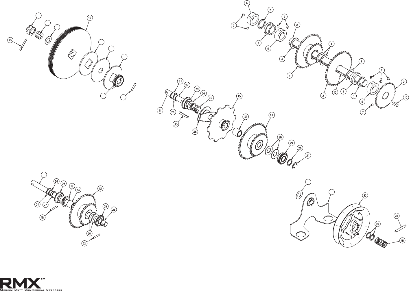
10.5
Shaft Assemblies
Appendix A (cont’)
www.overheaddoor.com 07/30/09
OUTPUT SHAFT ASSEMBLY
INTERMEDIATE SHAFT ASSEMBLY
(HOIST)
INTERMEDIATE SHAFT ASSEMBLY
(RELEASE)
HANDWHEEL KIT
CLUTCH KIT
23
14
24
16
17
17
30
31
20
34
11

10.6
Shaft Parts List
Item Part Number Kit Includes Description Qty
A 110970.0001 Clutch Kit
12 110469.0001 Pulley, Clutch 1
14 075197.0000 Spring, Clutch 1
16 075193.0000 Lining, Clutch 1
17 108015.0001 Disc, Clutch Movable 2
23 110472.0001 Nut 5/8-11 1
25 080401.0624 Pin, Cotter 1
30 110874.0001 Insert, Clutch Disc 1
31 110881.0001 Pin, Dowel 1
24 086649.0029 Washer, Thrust 1
N/S 110971.0001 Instructions 1
B 110984.0001 Output Shaft Kit - J/H Direct
1 110923.0002 Sprocket/Bushing Assy 1
2 110396.0003 Sprocket - 45T 1
3 110482.0003 Sprocket - 40T 1
4 110393.0001 Washer, Spacer 1" 4
5 110819.0002 Washer, Plain 1" 2
6 604297.4100 Set Collar 1" 3
7 080300.1604 Set Screw 8
8 110478.0003 Output Shaft 1
9 106064.0001 Bushing 2
10 080340.0074 Key 1/4 X 7/8 2
N/S 110966.0001 Grease 1
N/S 110985.0001 Instructions 1
C 110988.0001 Int. Shaft Kit - H Direct
11 110463.0001 Int. Shaft 1
13 110923.0001 Sprocket/Bushing Assy 1
19 110465.0001 Sprocket 11T #35 1
20 110391.0001 Washer, Spacer 5/8" 2
21 080415.0021 "E" Ring 5/8" 1
22 110313.0003 Pin, Spring 1
15 110313.0008 Pin, Spring 1
26 110819.0001 Washer, Plain 5/8" 4
27 110818.0001 Washer, Wave 5/8" 1
28 110313.0007 Pin, Spring 1
29 110813.0001 Bearing 5/8" 2
33 110820.0001 Bushing, Bronze - Spacer 1
N/S 110996.0001 Grease 1
N/S 110989.0001 Instructions 1
Item Part Number Kit Includes Description QtyItem Part Number Kit Includes Description Qty
D 110973-0001 Handwheel Kit
34 110411-0001 Chain Guard Assy 1
32 110872-0001 Handwheel Assy 1
18 110545-0001 Spring, Handwheel 1
28 110313-0007 Pin, Spring 1
20 110391-0001 Washer, Spacer 5/8" 1
26 110819-0001 Washer, Plain 2
N/S 110974-0001 Instructions 1
E 110992.0001 Shaft, Intmd, Jackshaft Assy - Direct
11 110392.0001 Shaft, Intmd, Jackshaft 1
13 110923.0001 Sprocket/Bushing Assy 1
15 110817.0001 Sprocket and Engagement Plate 1
20 110391.0001 Washer, Spacer 5/8" 2
21 080415.0021 Ring, Rtng, Ext, “E”, STL, 5/8" 2
22 110389.0001 Spring, Jackshaft Release 1
24 086649.0029 Washer, Thrust 1
26 110819.0001 Washer, Plain, 5/8" 2
27 110818.0001 Washer, Wave, 5/8" 1
29 110813.0001 Bearing, .625 ID 2
35 110816.0001 Key, Round End, .188" x 1.500" 1
36 110387.0001 Slider, Jackshaft, MX 1
37 110820.0001 Bushing, .627" ID x .88" LG 1
N/S 110993.0001 Instructions 1
Appendix A (cont’)
www.overheaddoor.com 07/30/09

10.7
Electric Box Exploded View
Appendix A (cont’)
www.overheaddoor.com 07/30/09
B
F
G
H
D
E
I
J
JACKSHAFT
DIFFERENCE
HOIST
JACKSHAFT
WIRING LAYOUT - HOIST

Appendix A (cont’)
10.8
Electric Box Parts List
Item Part Number Kit Includes Description Qty
A 110943.0001 Electric Box Assy, Sidemount 120V
A 110944.0001 Electric Box Assy, Sidemount 240V
B 110955-0001 Replacement Board Kit
35451R Board 1
110825.0001 Standoff, Locking 1
Not Shown 110922.0001 Jumper Stop 1
Not Shown 110922.0002 Jumper Ext Interlock 1
Not Shown 110859.0001 Hoist Interlock Jumper 1
24173F04 Screw 4
Not Shown 110959.0001 Instructions 1
C 110957.0001 Fuse Kit (Not Shown)
34004C0002 Fuse 2A 10
34004DR315 Fuse .3A 10
D 110950.0001 Hinge Kit
110423.0001 Hinge 2
24173F04 Screw 2
E 110951.0001 Latch Kit
110870.0001 Latch 1
24173F04 Screw 1
F 110962.0001 Capacitor Kit 79µF
110830.0001 Capacitor, 79µF 1
110868.0001 Clamp 1
24173F04 Screw 1
Item Part Number Kit Includes Description Qty
F 110963.0001 Capacitor Kit 19.5µF
110830.0002 Capacitor, 19.5µF 1
110868.0001 Clamp 1
24173F04 Screw 1
G 110958-0001 Limit Retainer Kit
110542.0001 Plate, Limit Retainer 1
110562.0001 Spring, Limit 2
110827.0001 Screw 2
Not Shown 110961.0001 Instructions 1
H 110968-0001 Limit Shaft Kit - Sidemount
111048.0001 Limit Shaft 1
110459.0001 Travel Nut 2
109876.0003 Retaining Ring 2
110550.0001 Limit Trigger 2
110823.0001 Retaining Ring, Push On 2
110818.0003 Washer 1
077538.0000 Bushing 3/8" 2
Not Shown 601332.0001 Sprocket 14T #25 3/8"B 1
Not Shown 110969.0001 Instructions 1
I 110945.0001 Limit Nut Assy
110459.0001 Travel Nut 1
110550.0001 Limit Trigger 1
110823.0001 Retaining Ring, Push On 1
www.overheaddoor.com 07/30/09

10.9
Electric Box Parts List (cont’)
Item Part Number Kit Includes Description Qty
J 110869.0002 Cover Assy
110505.0002 Cover 1
Not Shown 100270.0005 Decal 1
Not Shown 110851.0001 Decal 1
Not Shown 35571A Label 1
086575-0712 Screw 1
1 110429.0001 Box, Electric 1
2 110870.0001 Latch, Electric Box 1
3 603038.0012 Plug, hole, 7/8 2
4 110542.0001 Plate, Limit Retainer 1
5 110827.0001 Screw, THDF, #8-32 X 1, Hex Head 2
6 110562.0001 Spring, Limit 2
7 110423.0001 Hinge, Electric Box 2
8 24173F04 Scr, #6-32 X 3/8, SLFTPG, SEMS 12
9 110825.0001 Standoff, Circuit Board, Locking 1
10 110826.0001 Standoff, PEM, #6-32 4
11 35451R Circuit Board 1
12 110868.0001 Clamp, Capacitor 1
13 110828.0001 Standoff, Circuit Board, Support 6
14 8706E29 Screw, HHD, SLTD, TAP, #8-32 X 3/8 GN 2
15 110900.0001 Terminal Strip, 3 Position 1
16 605476.0003 Clip, Wire 2
17 110830.0001 Capacitor, 79 µF 1
110830.0002 Capacitor, 19.5 µF
18 110846.0001 Transformer, 120VAC 1
110846.0002 Transformer, 240VAC
19 111048.0001 Shaft, Limit 1
20 110459.0001 Nut, Travel 2
Item Part Number Kit Includes Description Qty
21 109876.0003 Retaining Ring 2
23 110550.0001 Limit Trigger 2
24 110823.0001 Retaining Ring, Push on 2
25 110818.0003 Washer, Wave Spring, .397 ID 1
26 077538.0000 Bushing, 3/8" ID 2
27 110505.0002 Cover, Electric Box 1
28 086575.0712 Screw, HH, SLTD, TF, # 10-24 X 3/4" 1
31 35709A Limit Ramp 2
32 110892.0001 HSG & Lead Assy., Radio 1
33 110922.0001 Lead & Label Assy, Stop Button 1
34 110922.0002 Lead & Label Assy, Interlock 1
35 110898.0001 Bag Assy, Fuse 1
36 110859.0001 HSG & Lead Assy., Jumper 1
37 110858.0001 HSG & Lead Assy., 2 Pos., Interlock 1
38 110857.0001 HSG & Lead Assy., 3 Pos., Brake 1
40 22327B Tie, Cable 1
41 107606.0002 Bushing, Snap, .500 (Jackshaft) 1
Bushing, Snap, .500 (Hoist) 2
42 603038.0006 Plug, 1/2" Hole (Jackshaft Only) 1
110930.0001 Instructions (not shown) 1
Appendix A (cont’)
www.overheaddoor.com 07/30/09
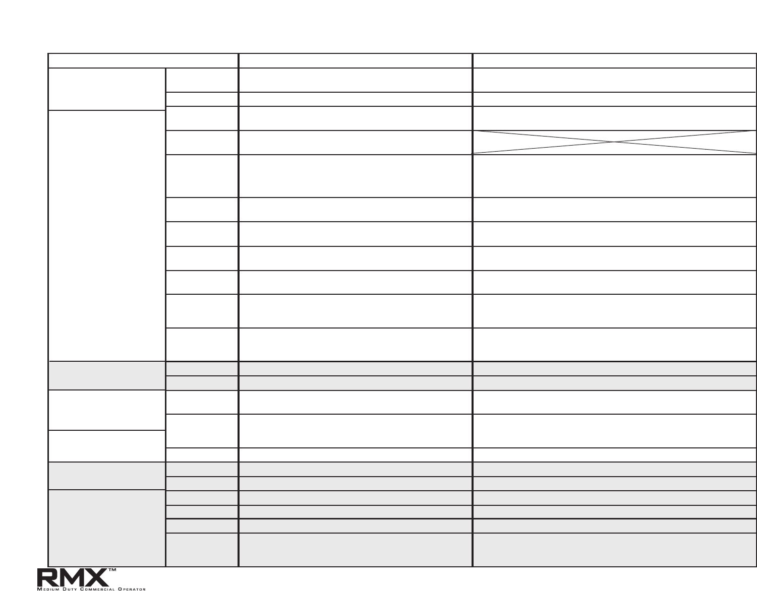
10.10
Section 10: Appendix B
Screw Terminal Assignments
FUNCTION CONNECTION TYPE
11-POSITION
TERMINAL BLOCK
INSIDE ELECTRIC BOX
OPEN
Causes door to open if not at Up Limit.
Causes a closing door to reverse.
Normally-Open Dry Contact to GND.
CLOSE
Causes door to close if not at Down Limit.
Normally-Open Dry Contact to GND.
STOP
Causes a moving door to stop.
Prevents the operator from running.
Normally-Closed Dry Contact to GND.
GND
Common ground connection for Open, Close, Stop &
1-Btn Inputs.
1-BTN
Causes door to open if not at Up Limit or Mid-Stop Limit.
Causes door to close if at Up Limit or Mid-Stop Limit.
Causes door to stop if opening.
Causes a closing door to reverse.
Normally-Open Dry Contact to GND.
ODC STB
Reverses a closing door if photocell beam is blocked.
NOTE: STB's must be enabled in Calibration Mode.
Connect only ODC Series II Safe-T-Beams® to these inputs.
Connect to either terminal (not polarity sensitive).
ODC STB
Reverses a closing door if photocell beam is blocked.
NOTE: STB's must be enabled in Calibration Mode.
Connect only ODC Series II Safe-T-Beams® to these inputs.
Connect to either terminal (not polarity sensitive).
N-O SAFETY
Causes a closing door to reverse.
NOTE: Will not open a stopped door.
Normally-Open 2-Wire Non-Monitored Edge Sensor
Connect to either terminal (not polarity sensitive)
N-O SAFETY
Causes a closing door to reverse.
NOTE: Will not open a stopped door.
Normally-Open 2-Wire Non-Monitored Edge Sensor
Connect to either terminal (not polarity sensitive)
EXT INTLK
Causes a moving door to stop.
Prevents the operator from running when contact is open.
Operates even if microcontroller is non-functional.
Normally-Closed dry contacts.
(board will energize these contacts at nominal +24VDC).
EXT INTLK
Causes a moving door to stop.
Prevents the operator from running when contact is open.
Operates even if microcontroller is non-functional.
Normally-Closed dry contacts.
(board will energize these contacts at nominal +24VDC).
2-POSITION TERMINAL
L1 / L1
Power to RMX™ operator.
120VAC: Connect to Line (Hot) / 240VAC: Connect to Line 1.
BLOCK INSIDE ELECTRIC BOX
N / L2
Power to RMX™ operator.
120VAC: Connect to Neutral / 240VAC: Connect to Line 2.
3-POSITION TERMINAL
STRIP
ON OUTSIDE OF
ELECTRIC BOX
PWR
Provides power for radio & other accessories.
+20 to +40VDC, fused at 315mA (F1).
Connect to radio or other accessory's power input.
RAD
GND
Causes door to open if not at Up Limit or Mid-Stop Limit.
Causes door to close if at Up Limit or Mid-Stop Limit.
Causes a closing door to reverse.
Common ground connection for PWR and RAD terminals. Connect to radio or other accessory's ground input.
EXPANSION PORT
Connects accessory modules to RMX™ operator.
Accessory Module Ribbon Cable.
PLUG CONNECTIONS
INSIDE ELECTRIC BOX
TRANSFORMER
Connects main transformer to control board.
Transformer Plug.
TRANSFORMER
Connects optional second transformer to control board.
Transformer Plug.
BRAKE
Connects brake solenoid to control board.
Brake Solenoid Plug.
MOTOR
Connects motor & capacitor to control board.
Motor Plug.
HOIST INTLK
Causes a moving door to stop.
Prevents the operator from running.
Operates even if microcontroller is non-functional.
Hoist Interlock Plug or Jumper.
INPUT
(Radio Input Control)
www.overheaddoor.com 07/30/09

10.11
Section 10: Appendix C
Display Run Codes
Condition
Code
DISPLAY
Condition Code Description
0C IDLE > DOWN LIMIT STANDING BY AT DOWN LIMIT (NOTE: THIS MESSAGE IS DISPLAYED IF BOTH LIMITS ARE ACTIVE)
0D
IDLE
>
UP LIMIT
STANDING BY AT UP LIMIT
0E IDLE
>
MID STOP STANDING BY AT MID-STOP LIMIT
0F
IDLE
>
NO LIMIT
STANDING BY BETWEEN LIMITS
10 OPENING
>
OPEN BTN OPENING FROM OPEN BUTTON
11 OPENING
>
ONE BTN OPENING FROM 1 BUTTON
12 OPENING
>
RADIO OPENING FROM RADIO
13 OPENING
>
AUX OPEN OPENING FROM AUXILIARY OPEN INPUT
14 OPENING
>
OPEN KEY OPENING FROM KEYPAD OPEN KEY
20 CLOSING
>
CLOSE PB CLOSING FROM CLOSE BUTTON
21 CLOSING
>
ONE BTN CLOSING FROM 1 BUTTON
22 CLOSING
>
RADIO CLOSING FROM RADIO
24 CLOSING
>
CLOSE KP CLOSING FROM KEYPAD CLOSE KEY
2A CLOSING
>
TCM CLS CLOSING FROM TIMER CLOSE MODULE
30 HALT
>
WALL BUTTON GDO STOPPED BECAUSE STOP OR OPEN BUTTON WAS ACTIVATED, POSSIBLY STARTING A REVERSAL
31 HALT
>
ONE BUTTON GDO STOPPED BECAUSE 1 BUTTON WAS ACTIVATED, POSSIBLY STARTING A REVERSAL
32 HALT
>
RADIO GDO STOPPED BECAUSE RADIO INPUT WAS ACTIVATED, STARTING A REVERSAL
33 HALT
>
AUX. OPEN GDO STOPPED BECAUSE AUXILIARY OPEN INPUT WAS ACTIVATED, STARTING A REVERSAL
34 HALT
>
KEYPAD KEY GDO STOPPED BECAUSE KEYPAD STOP OR OPEN KEY WAS ACTIVATED, POSSIBLY STARTING A REVERSAL
35 HALT
>
N-O SAFETY GDO STOPPED BECAUSE N-O REVERSING INPUT WAS ACTIVATED, STARTING A REVERSAL
36 HALT
>
ODC STB GDO STOPPED BECAUSE ODC STB WAS BLOCKED, STARTING A REVERSAL
37 HALT
>
N-C SAFETY GDO STOPPED BECAUSE N-C REVERSING INPUT WAS ACTIVATED, STARTING A REVERSAL
38 HALT
>
MON. EDGE GDO STOPPED BECAUSE MONITORED EDGE SENSOR INPUT WAS ACTIVATED, STARTING A REVERSAL
39 HALT
>
DOOR FORCE GDO STOPPED BECAUSE THE FORCE REQUIRED TO OPERATE THE DOOR WAS TOO HIGH, POSSIBLY STARTING A REVERSAL
3A HALT
>
LOSS OF C/C
GDO STOPPED BECAUSE CONSTANT CONTACT ON THE CONTROL WAS REMOVED BEFORE REACHING A LIMIT, POSSIBLY STARTING A REVERSAL
3B HALT
>
SHUTDOWN GDO STOPPED BECAUSE THE GDO DETECTED A FAULT SUCH AS AN OPEN INTERLOCK, OVERHEATED MOTOR, ETC.
3C HALT
>
DOWN LIMIT GDO STOPPED BECAUSE IT REACHED THE DOWN LIMIT
3D HALT
>
UP LIMIT GDO STOPPED BECAUSE IT REACHED THE UP LIMIT
3E HALT
>
MID STOP GDO STOPPED BECAUSE IT REACHED THE MID-STOP LIMIT
3F HALT
>
MODULE FAIL GDO STOPPED BECAUSE AN EXPANSION MODULE WAS NOT WORKING PROPERLY
www.overheaddoor.com 07/30/09

10.12
Display Error Codes
Section 10: Appendix C
Condition
Code
DISPLAY
Condition Code Description
40 REV
>
OPEN BUTTON GDO REVERSED BECAUSE THE OPEN BUTTON WAS ACTIVATED
41 REV
>
ONE BUTTON GDO REVERSED BECAUSE THE 1 BUTTON WAS ACTIVATED
42 REV
>
RADIO GDO REVERSED BECAUSE THE RADIO INPUT WAS ACTIVATED
43 REV
>
AUX OPEN GDO REVERSED BECAUSE THE AUXILIARY OPEN INPUT WAS ACTIVATED
44 REV
>
OPEN KEY GDO REVERSED BECAUSE THE KEYPAD OPEN KEY WAS ACTIVATED
45 REV
>
N-O SAFETY GDO REVERSED BECAUSE THE N-O REVERSING INPUT WAS ACTIVATED
46 REV
>
ODC STB GDO REVERSED BECAUSE THE ODC STB WAS BLOCKED
47 REV
>
N-C SAFETY GDO REVERSED BECAUSE THE N-C REVERSING INPUT WAS ACTIVATED
48 REV
>
MON. EDGE GDO REVERSED BECAUSE THE MONITORED EDGE SENSOR WAS ACTIVATED
49 REV
>
DOOR FORCE GDO REVERSED BECAUSE THE FORCE REQUIRED TO CLOSE THE DOOR WAS TOO HIGH
4A REV
>
LOSS OF C/C GDO REVERSED BECAUSE CONSTANT CONTACT ON THE CONTROL WAS REMOVED BEFORE REACHING THE DOWN LIMIT
4B REV
>
MAX RUN TMR GDO REVERSED BECAUSE THE CLUTCH SLIPPED OR SOME OTHER FAULT OCCURRED THAT ALLOWED THE GDO TO RUN TOO LONG
4F REV > EXP MOD FAIL GDO REVERSED BECAUSE AN EXPANSION MODULE WAS NOT WORKING PROPERLY
50 STOP
>
HOT MOTOR GDO STOPPED BECAUSE THE MOTOR WAS OVERHEATED
51 STOP
>
OPEN MRT GDO STOPPED BECAUSE THE CLUTCH SLIPPED OR SOME OTHER FAULT OCCURRED THAT ALLOWED THE GDO TO RUN OPEN TOO LONG
52 STOP
>
CLOSE MRT GDO STOPPED BECAUSE THE CLUTCH SLIPPED OR SOME OTHER FAULT OCCURRED THAT ALLOWED THE GDO TO RUN DOWN TOO LONG
57 STOP
>
OPEN INTLK GDO STOPPED BECAUSE THE HOIST INTERLOCK OR EXTERNAL INTERLOCK IS OPEN
58 STOP
>
WRONG GDO GDO STOPPED BECAUSE THE BOARD IS SET FOR JACKSHAFT MODE, BUT INSTALLED IN A TROLLEY OPERATOR
59 STOP
>
DOOR FORCE GDO STOPPED BECAUSE THE FORCE REQUIRED TO OPEN THE DOOR WAS TOO HIGH
5A STOP
>
WRONG LIMIT GDO STOPPED BECAUSE THE UP LIMIT ACTIVATED WHEN CLOSING OR THE DOWN LIMIT ACTIVATED WHEN OPENING
5C STALL
>
DOWN LIMIT GDO STOPPED BECAUSE IT COULDN'T LEAVE THE DOWN LIMIT DUE TO A SLIPPING CLUTCH OR OTHER PROBLEM
5D STALL
>
UP LIMIT GDO STOPPED BECAUSE IT COULDN'T LEAVE THE UP LIMIT DUE TO A SLIPPING CLUTCH OR OTHER PROBLEM
60 CHECK STOP BTN GDO WON'T RUN BECAUSE THE STOP BUTTON IS ACTIVE
61 TCM DISABLED TIMER CLOSE WON'T WORK BECAUSE NO SAFETIES ARE ENABLED
62 NO RADIO
>>
C/C RADIO INPUT WON'T WORK WITH OPEN OR CLOSE FUNCTION IN CONSTANT CONTACT MODE
63 CHECK AUX OPEN GDO WON'T CLOSE BECAUSE AUXILIARY OPEN INPUT IS ACTIVE
64 CHECK STOP KEY GDO WON'T RUN BECAUSE THE KEYPAD STOP KEY IS ACTIVE
65 CHECK N-O SAFETY GDO WON'T CLOSE BECAUSE THE N-O REVERSING IS ACTIVE
66 CHECK ODC STB GDO WON'T CLOSE BECAUSE THE ODC STB IS BLOCKED
67 CHECK N-C SAFETY GDO WON'T CLOSE BECAUSE THE N-C REVERSING INPUT IS ACTIVE
68 CHECK MON. EDGE GDO WON'T CLOSE BECAUSE THE MONITORED EDGE SENSOR IS ACTIVE
69 OVERHEATED MOTOR GDO WON'T RUN BECAUSE THE MOTOR IS OVERHEATED
6C NO RUN
>
DOWN LIM GDO WON'T CLOSE BECAUSE ITS ALREADY AT THE DOWN LIMIT
6D NO RUN
>
UP LIMIT GDO WON'T OPEN BECAUSE ITS ALREADY AT THE UP LIMIT
6E NO RUN
>
MID STOP GDO WON'T RUN BECAUSE ITS AT OR ABOVE THE MID-STOP LIMIT & CAN'T RUN UP & A REVERSING INPUT IS PREVENTING IT FROM CLOSING
6F EXP MODULE FAIL GDO WON'T RUN BECAUSE AN EXPANSION MODULE FAILURE IS PREVENTING IT
www.overheaddoor.com 07/30/09

10.13
Display Error Codes (cont’)
Section 10: Appendix C
Condition
Code
DISPLAY
Condition Code Description
70 BOARD FAILURE 70 CONTROL BOARD FAILURE 70, CONTACT FACTORY TECHNICAL SERVICE DEPT.
71 BOARD FAILURE 71 CONTROL BOARD FAILURE 71, CONTACT FACTORY TECHNICAL SERVICE DEPT.
74 BOARD FAILURE 74 CONTROL BOARD FAILURE 74, CONTACT FACTORY TECHNICAL SERVICE DEPT.
75 BOARD FAILURE 75 CONTROL BOARD FAILURE 75, CONTACT FACTORY TECHNICAL SERVICE DEPT.
76 BOARD FAILURE 76 CONTROL BOARD FAILURE 76, CONTACT FACTORY TECHNICAL SERVICE DEPT.
77 BOARD FAILURE 77 CONTROL BOARD FAILURE 77, CONTACT FACTORY TECHNICAL SERVICE DEPT.
80 BOARD FAILURE 80 CONTROL BOARD FAILURE 80, CONTACT FACTORY TECHNICAL SERVICE DEPT.
81 BOARD FAILURE 81 CONTROL BOARD FAILURE 81, CONTACT FACTORY TECHNICAL SERVICE DEPT.
82 BOARD FAILURE 82 CONTROL BOARD FAILURE 82, CONTACT FACTORY TECHNICAL SERVICE DEPT.
83 BOARD FAILURE 83 CONTROL BOARD FAILURE 83, CONTACT FACTORY TECHNICAL SERVICE DEPT.
84 BOARD FAILURE 84 CONTROL BOARD FAILURE 84, CONTACT FACTORY TECHNICAL SERVICE DEPT.
85 EXP PORT PROBLEM EXPANSION PORT IS SHORT CIRCUITED, TRY DISCONNECTING EXPANSION MODULES OR CONTACT FACTORY TECHNICAL SERVICE DEPT.
86 BOARD FAILURE 86 CONTROL BOARD FAILURE 86, DISCONNECT EXPANSION MODULES. IF NO CHANGE, CONTACT FACTORY TECHNICAL SERVICE DEPT.
88 TCM FAILURE TIMER CLOSE MODULE (TCM) HAS FAILED
8A AOM FAILURE AUXILIARY OUTPUT MODULE (AOM) HAS FAILED
8E REV INTERRUPTED GDO LOST POWER OR ENCOUNTERED ANOTHER PROBLEM DURING THE REVERSAL PROCESS, REVERSAL IS COMPLETING NOW
8F LIMIT MOD. FAIL GDO WON'T RUN, LIMIT MODULE HAS FAILED
90 DIAGNOSTIC MODE GDO IS IN DIAGNOSTIC MODE, NORMAL FUNCTIONS ARE NOT ALLOWED
A0 OPEN BTN BAD
>
PU OPEN & CLOSE BUTTONS WON'T WORK, THE OPEN BUTTON WAS ACTIVE WHEN THE GDO WAS POWERED-UP
A1 CLOSE BTN BAD
>
PU OPEN & CLOSE BUTTONS WON'T WORK, THE CLOSE BUTTON WAS ACTIVE WHEN THE GDO WAS POWERED-UP
A2 ONE BTN BAD
>
PU 1 BUTTON WON'T WORK, THE 1 BUTTON WAS ACTIVE WHEN THE GDO WAS POWERED-UP
A3 RADIO BAD
>
PWR UP RADIO INPUT WON'T WORK, THE RADIO INPUT WAS ACTIVE WHEN THE GDO WAS POWERED-UP
A4 AUX OPEN BAD
>
PU AUXILIARY OPEN INPUT WON'T WORK, THE AUXILIARY OPEN INPUT WAS ACTIVE WHEN THE GDO WAS POWERED-UP
A5 OPEN KEY BAD
>
PU KEYPAD OPEN & CLOSE KEYS WON'T WORK, THE OPEN KEY WAS ACTIVE WHEN THE GDO WAS POWERED-UP
A6 CLOSE KEY BAD
>
PU KEYPAD OPEN & CLOSE KEYS WON'T WORK, THE CLOSE KEY WAS ACTIVE WHEN THE GDO WAS POWERED-UP
A7 MULT KEYS BAD
>
PU 1 OR MORE KEYPAD CALIBRATION KEYS WON'T WORK, 1 OR MORE WERE ACTIVE WHEN THE GDO WAS POWERED-UP
AA TCM BAD
>
POWER UP TIMER CLOSE MODULE WON'T CLOSE DOOR, IT WAS ACTIVE WHEN THE GDO WAS POWERED-UP
www.overheaddoor.com 07/30/09
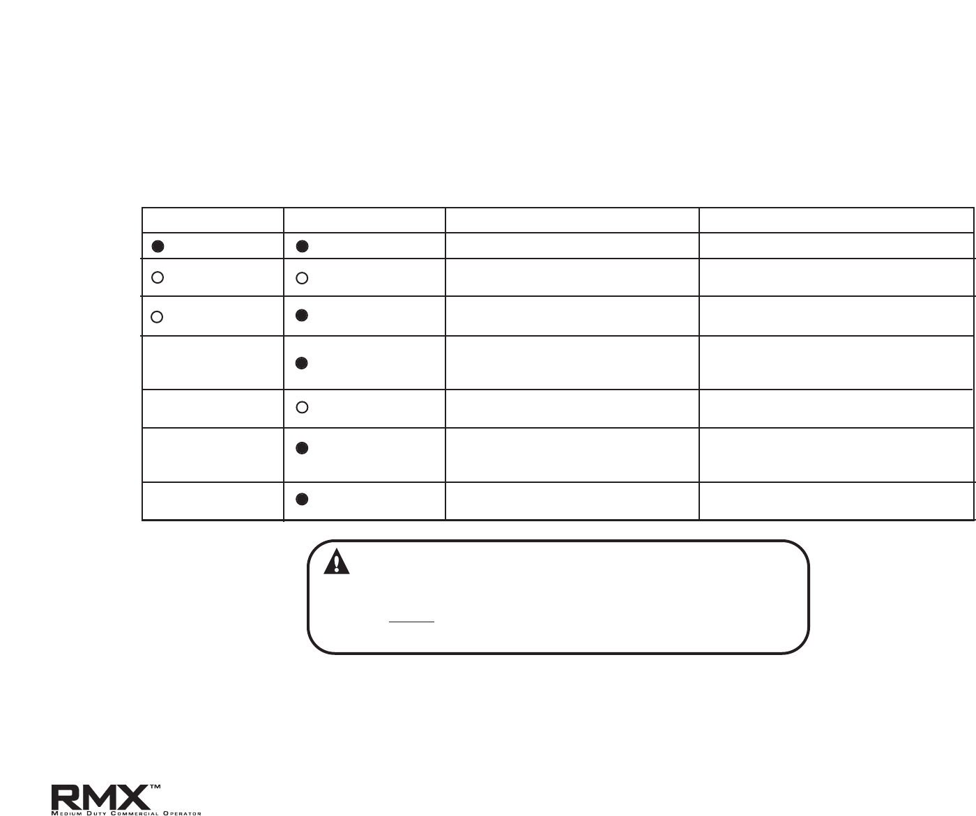
ON
ON
NORMAL OPERATION
NONE REQUIRED
OFF
OFF
1. POWER HEAD NOT POWERED
2. WIRING FROM POWER HEAD BAD
1. CHECK BREAKERS, FUSES, PLUGS
2. CHECK WIRING FOR OBVIOUS SHORTS
OFF
ON
1. WIRING TO SOURCE MISSING OR BAD
2. POWER HAS BEEN INTERRUPTED
1. CHECK WIRING
2. REMOVE POWER AND REAPPLY
2 BLINKS, PAUSE
(REPEAT)
ON
1. BEAM NOT ALIGNED
2. BEAM OBSTRUCTED
3. SENSOR DEFECTIVE
1.CHECK ALIGNMENT
2. CHECK FOR OBSTRUCTION
3. CALL CUSTOMER SERVICE
1. WIRE TO SENSOR MISSING OR BAD
2. SENSOR DEFECTIVE
1. CHECK WIRING
2. CALL CUSTOMER SERVICE
OFF
ON
1. SENSOR RECEIVING INTERFERENCE
1.
ATTEMPT TO DETERMINE SOURCE OF
INTERFERENCE
2. CALL CUSTOMER SERVICE
ON
1. SOURCE NOT SENDING PULSES
2. SOURCE DEFECTIVE
1. CALL CUSTOMER SERVICE
2. CALL CUSTOMER SERVICE
SOURCE
(
RED LED
)
SENSOR
(
GREEN LED
)
INDICATED CONDITION
REQUIRED ACTION
2 BLINKS, PAUSE
(REPEAT
)
3 BLINKS, PAUSE
(REPEAT)
4 BLINKS, PAUSE
(REPEAT)
Safe-T-Beam® Monitored Photocell Self-diagnostic Troubleshooting Chart
Section 10: Appendix D
10.14
WARNING:
ACTUATING THE OPERATOR BY USING CONSTANT CONTACT ON
THE CL
OSE BUTTON WILL OVERRIDE EXTERNAL REVERSING
DEVICES, INCLUDING PHOTOCELLS.
www.overheaddoor.com 07/30/09

Access Systems Division
a Division of Overhead Door Corporation
22790 Lake Park Blvd.
Alliance, Ohio 44601

©Overhead Door Corporation Operation & Maintenance Manual: Commercial Operators
WARRANTY

C900-974
M
®
The authorized distributor of Overhead Door Corporation products, whose name appears below ("Seller") warrants
to the original purchaser of model RMX
®
commercial operators ("Product"), subject to all of the terms and conditions
hereof, that the Product and all components thereof will be free from defects in materials and workmanship under
normal use for the following period(s), measured from the date of installation:
• Two (2) years or 20,000 cycles*, whichever occurs first.
Seller’s obligation under this warranty is specifically limited to repairing or replacing, at its option, any part which
is determined by Seller to be defective during the applicable warranty period. Any labor charges are excluded and will
be the responsibility of the purchaser.
This warranty is made to the original purchaser of the Product only, and is not transferable or assignable. This warranty
applies only to an operator which is installed in commercial or industrial building applications. This warranty does not
apply to any unauthorized alteration or repair of the Product, or to any Product or component which has been damaged
or deteriorated due to misuse, neglect, accident, failure to provide necessary maintenance, normal wear and tear, or acts
of God or any other cause beyond the reasonable control of Seller.
THIS WARRANTY IS EXCLUSIVE AND IN LIEU OF ANY OTHER WARRANTIES, EITHER EXPRESS OR
IMPLIED, INCLUDING BUT NOT LIMITED TO ANY IMPLIED WARRANTY OF MERCHANTABILITY OR
FITNESS FOR A PARTICULAR PURPOSE.
IN NO EVENT SHALL SELLER BE RESPONSIBLE FOR, OR LIABLE TO ANYONE FOR, SPECIAL,
INDIRECT, COLLATERAL, PUNITIVE, INCIDENTAL OR CONSEQUENTIAL DAMAGES, even if Seller has
been advised of the possibility of such damages. Such excluded damages include, but are not limited to, loss of
goodwill, loss of profits, loss of use, cost of any substitute product, interruption of business, or other similar indirect
financial loss.
Claims under this warranty must be made promptly after discovery, within the applicable warranty period, and in
writing to the Seller or to the authorized distributor or installer whose name and address appear below. The purchaser
must allow Seller a reasonable opportunity to inspect any Product claimed to be defective prior to removal or any
alteration of its condition. Proof of the purchase and/or installation date, and identification as the original purchaser,
may be required.
ORIGINAL PURCHASER
INSTALLATION ADDRESS
SELLER:
SELLER’S ADDRESS:
FACTORY ORDER #:
DATE OF INSTALLATION:
SIGNATURE OF SELLER:
*The number of cycles referred to herein shall be measured by an integrated cycle counter contained in or attached to the Product. If the cycle counter is rendered
inoperable Seller shall use other reasonable means to determine cycle count.