User
Manual
GFK-2308W
May 2021
PACSystems™ RX3i Hot Standby
CPU Redundancy

Warnings and Caution Notes as Used in this Publication
WARNING
Warning notices are used in this publication to emphasize that hazardous voltages, currents,
temperatures, or other conditions that could cause personal injury exist in this equipment or may be
associated with its use.
In situations where inattention could cause either personal injury or damage to equipment, a Warning
notice is used.
CAUTION
Caution notices are used where equipment might be damaged if care is not taken.
Note: Notes merely call attention to information that is especially significant to understanding and
operating the equipment.
These instructions do not purport to cover all details or variations in equipment, nor to provide for
every possible contingency to be met during installation, operation, and maintenance. The
information is supplied for informational purposes only, and Emerson makes no warranty as to the
accuracy of the information included herein. Changes, modifications, and/or improvements to
equipment and specifications are made periodically and these changes may or may not be reflected
herein. It is understood that Emerson may make changes, modifications, or improvements to the
equipment referenced herein or to the document itself at any time. This document is intended for
trained personnel familiar with the Emerson products referenced herein.
Emerson may have patents or pending patent applications covering subject matter in this document.
The furnishing of this document does not provide any license whatsoever to any of these patents.
Emerson provides the following document and the information included therein as-is and without
warranty of any kind, expressed or implied, including but not limited to any implied statutory
warranty of merchantability or fitness for particular purpose.
PACSystems™ RX3i Hot Standby CPU Redundancy User Manual Contents
GFK-2308W May 2021
Contents iii
Contents
Section 1: Introduction ..................................................... 1
1.1 Hot Standby CPU Redundancy ..................................................................... 1
1.2 PACSystems HSB Redundancy Feature Summary ......................................... 4
1.3 Online Programming ................................................................................... 6
1.4 Online Repair and System Upgrade .............................................................. 6
1.5 Definitions................................................................................................... 6
1.6 PROFINET Definitions .................................................................................. 8
1.7 Revisions in this Manual ............................................................................. 11
1.8 Documentation ......................................................................................... 12
1.8.1 RX3i Manuals .................................................................................. 12
1.8.2 VersaMax Manuals .......................................................................... 12
Section 2: RX3i Hot Standby Redundancy Quick Start with
PROFINET I/O ...................................................................... 13
Section 3: RX3i Hot Standby Redundancy Quick Start with
Ethernet I/O 21
Section 4: System Configuration ..................................... 28
4.1 Components of a Hot Standby Redundancy System .................................. 28
4.1.1 Core Systems .................................................................................. 28
4.1.2 Redundant CPU Modules ................................................................. 29
4.1.3 Redundancy Memory Xchange Modules .......................................... 31
4.1.4 Redundant I/O Systems ................................................................... 32
4.1.5 Local I/O .......................................................................................... 33
4.2 CPU Redundancy Using PROFINET I/O ........................................................ 33
4.2.1 Configuration Considerations .......................................................... 33
4.2.2 Configuration Overview .................................................................. 34
4.2.3 PROFINET Network Architectures .................................................... 35
4.3 CPU Redundancy Using Ethernet NIU Remote I/O ...................................... 37
4.3.1 Dual Controller, Single LAN Systems ................................................ 37
4.3.2 Dual Controller, Dual LAN Systems .................................................. 39
4.4 Genius Hot Standby Operation .................................................................. 40
4.4.1 Genius Output Control .................................................................... 40
4.4.2 Basic CPU Redundancy Using Genius I/O ......................................... 40
Section 5: Configuration Requirements .......................... 45
5.1 Overview ................................................................................................... 45
5.1.1 Setting up a CPE400 or CPL410 for Redundancy .............................. 46
5.1.2 Setting up a CPE330 for Redundancy ............................................... 51
5.2 PROFINET I/O Configuration ...................................................................... 55
5.2.1 Requirements ................................................................................. 55
5.2.2 Restrictions ..................................................................................... 55
5.2.3 Generating the Hardware Configuration ......................................... 56
5.2.4 Downloading PROFINET I/O Configuration to the HSB CPU
Redundancy System ........................................................................ 62
5.2.5 Adding or Modifying a PROFINET I/O Device without Stopping the
Process ........................................................................................... 64
5.3 Using the Redundancy Wizards ................................................................. 73
5.3.1 Synchronizing the Hardware Configurations ................................... 74
PACSystems™ RX3i Hot Standby CPU Redundancy User Manual Contents
GFK-2308W May 2021
Introduction iv
5.4 Hardware Configuration Parameters ......................................................... 75
5.4.1 CPU Parameters .............................................................................. 75
5.4.2 Scan Parameters ............................................................................. 75
5.4.3 Redundancy Memory Xchange Module Parameters ......................... 82
5.4.4 Ethernet Interface Parameters ......................................................... 82
5.4.5 Rack Module Configuration Parameters .......................................... 84
5.4.6 Genius Bus Configuration ................................................................ 85
5.5 Adding Individual Variables to the Transfer Lists ........................................ 86
5.5.1 Mapped Variables ........................................................................... 87
5.5.2 Arrays ............................................................................................. 87
5.5.3 Instance Data Structure Variables .................................................... 87
5.5.4 Using the Variable Transfer List Report ............................................ 87
5.6 Storing (Downloading) Hardware Configuration ........................................ 89
5.7 Run Mode Store ......................................................................................... 90
5.7.1 Dual RMS with Simultaneous Activation in Redundant Systems ....... 90
5.7.2 Initial RMS Followed by Dual RMS .................................................... 91
5.7.3 RMS Operational Errors ................................................................... 92
5.7.4 Behavior of EGD in a Dual RMS ......................................................... 94
5.7.5 Hardware Configuration and Logic Coupling ................................... 94
Section 6: Operation ....................................................... 95
6.1 Power-up of a Redundant CPU ................................................................... 95
6.1.1 Synchronizing the Time of Day Clocks ............................................. 96
6.1.2 Validity of PROFINET I/O at Power-up .............................................. 97
6.2 Synchronizing Redundant CPUs ................................................................. 97
6.2.1 Dual Synchronization ...................................................................... 98
6.2.2 Resynchronization .......................................................................... 98
6.2.3 Operation when a Redundancy Link is Removed .............................. 98
6.3 %S References for CPU Redundancy ........................................................... 99
6.3.1 Redundancy Status Presented as OPC UA Variables ....................... 100
6.4 Scan Synchronization .............................................................................. 101
6.4.1 Synchronization of PROFINET I/O .................................................. 101
6.5 Fail Wait Time .......................................................................................... 102
6.6 Data Transfer ........................................................................................... 102
6.6.1 Synchronization and Data Transfer Process ................................... 102
6.6.2 Estimating Data Transfer Time ...................................................... 103
6.6.3 Programming a Data Transfer from Backup Unit to Active Unit
(SVC_REQs 27 & 28) ...................................................................... 107
6.6.4 Disabling Data Transfer Copy in Backup Unit (SVC_REQ 43) ........... 108
6.6.5 Validating the Backup Unit (SVC_REQ 43) ..................................... 111
6.7 Switching Control to the Backup Unit ...................................................... 111
6.7.1 PROFINET I/O Switchovers ............................................................. 112
6.7.2 Switching Times and Impact to Sweep Time .................................. 112
6.7.3 Commanding a Role Switch from the Application Program (SVC_REQ
26) ................................................................................................ 113
6.7.4 Implementing Preferred Master Using SVC_REQ 26....................... 114
6.8 STOP to RUN Mode Transition ................................................................. 114
6.8.1 Behavior with PROFINET I/O when No Healthy Redundancy Links are
Available ....................................................................................... 114
6.8.2 Validity of PROFINET I/O Immediately after a Configuration Download
116
6.9 RUN with Outputs Disabled Mode ........................................................... 116
6.10 RUN to STOP Mode Transition ................................................................. 117
PACSystems™ RX3i Hot Standby CPU Redundancy User Manual Contents
GFK-2308W May 2021
Introduction v
6.10.1 Behavior with PROFINET I/O when no Healthy Redundancy Links are
Available ....................................................................................... 117
6.11 Error Checking and Correction ................................................................. 118
6.12 Timer and PID Functions .......................................................................... 118
6.13 Timed Contacts ....................................................................................... 119
6.14 Multiple I/O Scan Sets .............................................................................. 119
6.15 Genius Bus Controller Switching .............................................................. 119
6.16 Redundant IP Addresses .......................................................................... 120
6.16.1 Validation and Activation of Redundant IP Addresses .................... 120
6.16.2 Monitoring and Deactivation of Redundant IP Address .................. 121
6.16.3 Operation of Redundant IP Address if both Redundancy Links Fail . 122
6.17 Ethernet Global Data in an HSB Redundancy System ................................ 123
6.17.1 Ethernet Global Data Production ................................................... 123
6.17.2 Ethernet Global Data Consumption ............................................... 125
Section 7: Faults ........................................................... 126
7.1 Fault Response ........................................................................................ 126
7.1.1 Faults for PROFINET I/O ................................................................. 127
7.2 Fault Actions ........................................................................................... 127
7.2.1 Configuration of Fault Actions ....................................................... 129
7.2.2 Configurable Fault Groups ............................................................. 130
7.2.3 Non-Configurable Fault Groups ..................................................... 131
7.2.4 Fatal Faults on Both Units in the Same Sweep ................................ 132
7.3 Controller Fault Table Messages for Redundancy ..................................... 132
7.3.1 Redundancy Fault Group (138) ...................................................... 132
7.3.2 Other Fault Groups ........................................................................ 136
7.4 Redundancy Link Failures ......................................................................... 137
7.4.1 Redundancy Memory Xchange Module Hardware Failure .............. 137
7.4.2 Redundancy Link Communications Failures ................................... 138
7.4.3 When the Last Redundancy Link Fails............................................. 138
7.4.4 CPE400/CPL410 Redundant Link Recovery .................................... 139
7.5 Online Repair and System Upgrade .......................................................... 139
7.5.1 Online Repair Recommendations .................................................. 140
7.5.2 Hot Swapping of Modules (RX3i Systems Only) ............................. 140
7.5.3 Hot Swapping Controllers (CRU320 to CPE330) ............................. 141
7.5.4 System CPU Upgrade .................................................................... 141
7.5.5 Online Repair of the Genius Bus ..................................................... 142
7.5.6 Repair of a Non-Synchronized Active Unit (NSAU) Split Control System
143
Appendix A RX3i Dual Genius Bus Overview ...................... 145
A 1.1 Features ........................................................................................ 145
A 1.2 Templates ..................................................................................... 145
A 1.3 Available Templates ...................................................................... 147
A 1.4 How to Choose a Template ........................................................... 147
Appendix B RX3i Dual Bus Genius Functionality ................. 148
Appendix C Switching Control to the Backup Unit When it has
Better PROFINET Connectivity than the Active Unit ........... 149
C 1.1 Overview ....................................................................................... 149
C 1.2 Application Examples .................................................................... 149
Appendix D Redundant I/O Wiring Details And Programming
Strategies 154
PACSystems™ RX3i Hot Standby CPU Redundancy User Manual Contents
GFK-2308W May 2021
Introduction vi
D 1.1 Introduction .................................................................................. 154
D 1.2 Redundant I/O Wiring Details ........................................................ 154
D 1.3 Dual Redundant Discrete Inputs With Dual Redundant Field Device
155
D 1.4 Dual Redundant Discrete Inputs With Single Field Device .............. 156
D 1.5 Dual Redundant Analogue Inputs With Dual Redundant Field Device
157
D 1.6 Dual Redundant Analogue Inputs With Single Field Device ............ 158
D 1.7 Dual Redundant Discrete Outputs with Single Field Device ............ 159
D 1.8 Dual Redundant Analogue Outputs With Single Field Device ......... 160
D 1.9 Dual Redundant Outputs With Single Field Device And Input Feedback
161
D 1.10Redundant Power Supply Wiring ................................................... 162
D 1.11Alternatives to Diodes ................................................................... 162
D 1.12Redundant I/O Programming Strategies ........................................ 163
D 1.13Dual Redundant Discrete Inputs .................................................... 163
D 1.14Dual Redundant Analogue Inputs .................................................. 164
D 1.15Dual Redundant Outputs ............................................................... 164
D 1.16Dual Redundant Outputs With Input Feedback .............................. 164
D 1.17Glossary ........................................................................................ 165
General Contact Information ................................................................... 166
Technical Support ................................................................................... 166

PACSystems™ RX3i Hot Standby CPU Redundancy User Manual Section 1
GFK-2308W May 2021
Introduction 1
Section 1: Introduction
This manual is a reference to the hardware components, configuration,
programming and operation of Hot Standby CPU redundancy for the PACSystems
RX3i. The information in this manual is intended to supplement the system
installation, programming, and configuration information contained in the manuals
listed under Related Documents.
1.1 Hot Standby CPU Redundancy
Hot Standby CPU Redundancy allows a critical application or process to continue
operating should a failure occur in any single component. A Hot Standby system uses
two CPUs: an Active unit that actively controls the process, and a Backup unit that is
synchronized with the Active unit and can take over the process if it becomes
necessary. The two units are synchronized when both are in Run Mode: the Backup
unit will have received the latest status and synchronization information from the
Active unit via a redundancy link, and each is running its logic solution in parallel.
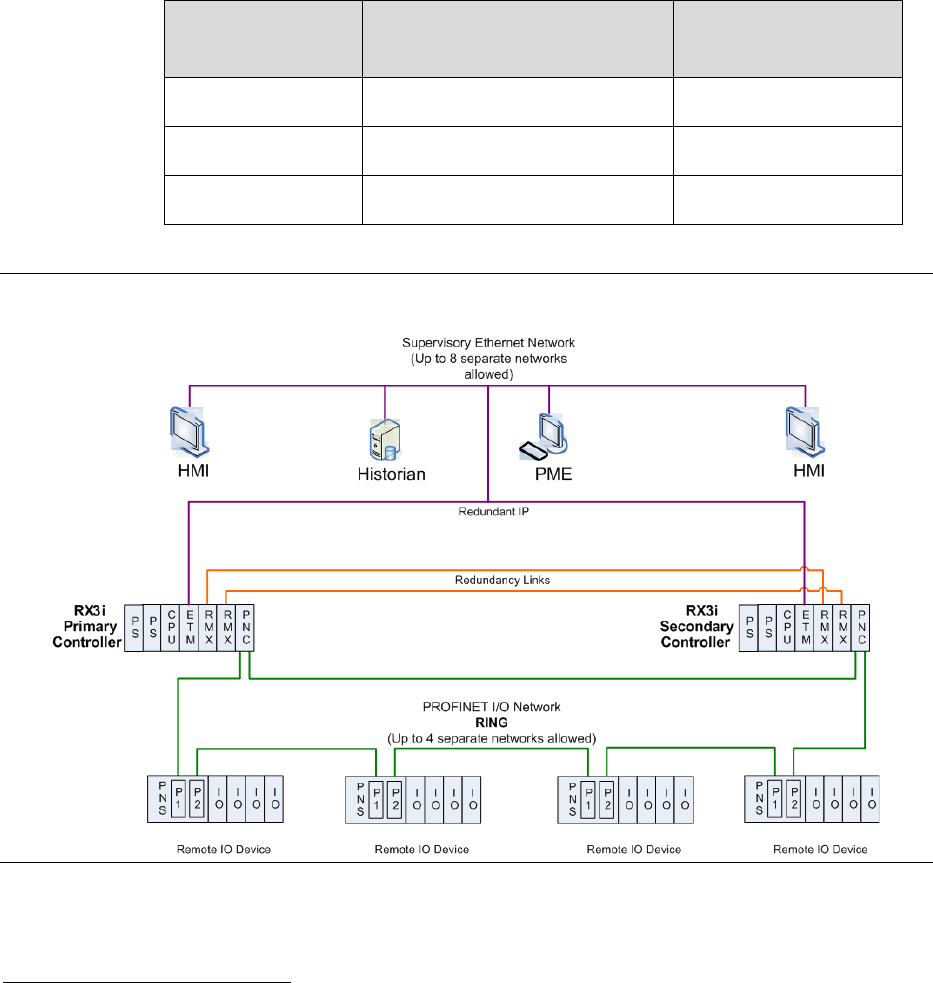
There are two distinctly different set-ups for Redundancy:
Traditional rack-mounted RX3i CPU systems (including CPE330), which require that
Redundancy Memory Xchange (RMX) modules be installed in each CPU rack. The
redundancy communication path is provided by a pair of RMX modules, one in the
rack of the Active (Primary) CPU, one in the rack of the Backup (Secondary) CPU. A
second pair of RMX modules may be used to create a redundant communication link.
Refer to Figure 1 for a traditional system, and to Figure 2 for a CPE330 system.
CPE400 and CPL410 do not use RMX modules. Rather, they use their own built-in
LAN3 ports to support the required redundancy communications links between
Primary and Secondary. LAN3 is a dedicated, secure, point-to-point Ethernet link
which does not support any additional equipment. Only a pair of CPE400 CPUs may
be interconnected on LAN3, as shown in Figure 3. Similarly, only a pair of CPL410
CPUs may be interconnected if using CPL410.
Note: In redundancy systems, we strongly recommend using a second
communications link, as shown in Figure 1 thru Figure 3. In Figure 1 and Figure 2, two
pairs of RMX modules configured as dual redundancy links are used. In Figure 3 each
CPU is connected to the other via both ports on LAN3. This practice eliminates the
possibility of a single point of failure that using only one communication link
presents.
Control automatically switches to the Backup unit when a failure is detected in the
Active unit. The user can initiate a switch of control by activating a toggle switch on
the RMX module or by activating a service request in the application program. When
a user-initiated switch of control occurs, the CPUs switch roles; the Active unit
becomes the Backup unit and the Backup unit becomes the Active unit.
The system runs synchronously with a transfer of all control data that defines
machine status and any internal data needed to keep the two CPUs operating in sync.
Critical control data plus all redundant outputs must be included in the output data
transfer. The transfer of data from the Active unit to the Backup unit occurs twice per
PACSystems™ RX3i Hot Standby CPU Redundancy User Manual Section 1
GFK-2308W May 2021
Introduction 2
sweep, once before the logic is solved and once after the logic is solved. These CPU-
to-CPU transfers are checked for data integrity.
The Primary and Secondary CPUs in a redundancy system must be in the same
Controller family. An RX3i Controller cannot function as a redundant pair. Similarly,
CPE400 must be paired with CPE400, CPL410 with CPL410, and CPE330 with
CPE330
1
.
The following versions of CPU firmware are required to support Redundancy:
Table 1: Support
CPU Type
Minimum Firmware Version
Required
PACPAC Machine
Edition Support
CPL410
Any
Release 9.50 SIM 10
CPE400
Release 9.30 Build E8JL
Release 9.50 SIM 5
CPE330
Release 8.70 Build E5KG
Release 8.60 SIM 8
Figure 1: Rack-Mounted CPU with RMX Redundancy Communications Links
1
Exception: A CPE330 replacing a CRU320 in a redundant system may be paired with a CRU320. This should be considered a temporary
arrangement. See notes in Section 6.2.1 and Section 6.8.1.
PACSystems™ RX3i Hot Standby CPU Redundancy User Manual Section 1
GFK-2308W May 2021
Introduction 3
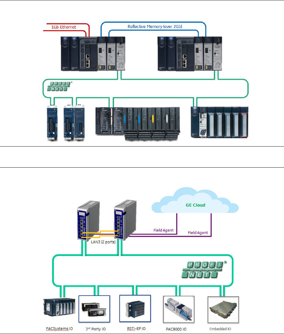
Figure 2: CPE330 Redundancy (Uses RXM modules for Redundancy Communications Link
Figure 3: CPE400 Redundancy (Uses LAN3 Ports for Redundancy Communications Link)

PACSystems™ RX3i Hot Standby CPU Redundancy User Manual Section 1
GFK-2308W May 2021
Introduction 4
1.2 PACSystems HSB Redundancy Feature
Summary
Feature
RX3i Redundancy System
CPE330 Redundancy
System
CPE400 or CPL410
Redundancy System
Redundant CPU
IC695CRU320
IC695CPE330
IC695CPE400 or
IC695CPL410
Redundancy links
Two IC695RMX128 or
IC695RMX228 modules per link
Two links (four RMX modules)
recommended per system
Two IC695RMX128 or
IC695RMX228 modules
per link
Two links (four RMX
modules) recommended
per system
2
LAN3 RDN
(Uses two lower ports on
faceplate)
Two links recommended per
system
Redundancy I/O
systems supported
PROFINET I/O using single ring and
star network topologies
Single and redundant Ethernet
remote
I/O LANs through ENIU
Single Bus and Dual Bus Genius
networks
PROFINET I/O using single
ring and star network
topologies
Single and redundant
Ethernet remote
I/O LANs through ENIU
Single Bus and Dual Bus
Genius networks
PROFINET I/O using single ring
and star network topologies
FUTURE: Single and redundant
Ethernet remote
I/O LANs through ENIU
Expansion and
remote racks
Supported
Supported
Not Supported
Failure recovery
Survives any one single point of
failure (excluding failures of Genius
devices and bus stubs)
Online repair of failed component
Survives any one single
point of failure (excluding
failures of Genius devices
and bus stubs)
Online repair of failed
component
Survives any one single point
of failure
Online repair of failed
component
Role switching
Manual toggle switch for switching
control between Active and
Backup units
Application-initiated role switching
Manual toggle switch for
switching control between
active and backup units
Application-initiated role
switching
OLED Display command for
switching control between
active and backup units
Application-initiated role
switching
2
While two links are recommended in a CPE330 Redundancy System, as of PME Release 9.5 SIM14 and firmware 9.75, the system can
be configured with only one link.

PACSystems™ RX3i Hot Standby CPU Redundancy User Manual Section 1
GFK-2308W May 2021
Introduction 5
Feature
RX3i Redundancy System
CPE330 Redundancy
System
CPE400 or CPL410
Redundancy System
Bumpless switching
from Active unit to
Backup unit
Synchronized CPUs
One-scan switching
Configurable transfer data size up
to 2Mbytes
Synchronized CPUs
One-scan switching
Configurable transfer data
size up to 2Mbytes
Synchronized CPUs
One-scan switching
Configurable transfer data size
up to 2Mbytes
Redundancy status
monitoring
RMX128/RMX228 module has five
redundancy status LEDs (Link OK,
Local Ready, Local Active, Remote
Ready, Remote Active)
Redundancy status bits and
message logging
RMX128/RMX228 module
has five redundancy status
LEDs (Link OK, Local
Ready, Local Active,
Remote Ready, Remote
Active)
Redundancy status bits
and message logging
OLED Display provides
redundancy state. CPE400 &
CPL410 also include two
redundancy status LEDs: RACT
(Local Unit Ready & Active),
and RBOK (Remote Unit
Ready)
Redundancy status bits and
message logging
Online programming
Supported
Supported
Supported
Diagnostics
Background diagnostics
Memory error checking and
correction (ECC) with single bit
corrections and multiple bit
checking
Background diagnostics
Memory error checking
and correction (ECC) with
single bit corrections and
multiple bit checking
Background diagnostics
Memory error checking and
correction (ECC) with single
bit corrections and multiple
bit checking
Maximum fiber-optic
cable distance
supported between
two devices used in
redundancy link
RMX128: 1000 ft (304.8m)
RMX228: 6.2 mi (10 km)
RMX128: 1000 ft (304.8m)
RMX228: 6.2 mi (10 km)
100 meters (328 ft).

PACSystems™ RX3i Hot Standby CPU Redundancy User Manual Section 1
GFK-2308W May 2021
Introduction 6
1.3 Online Programming
On-line changes to the application program are permitted in both the Active unit and
the Backup unit. The programming device must be connected to the unit in which
changes are to be made in order to make any on-line changes.
PACSystems releases 5.5 and later supports Run Mode Store (RMS) of the redundancy
Transfer List. This capability allows you to add, delete or modify Transfer List entries
without stopping the controllers.
Run Mode Store is performed independently on each controller. However, in a
synchronized system, the optional Dual RMS with Simultaneous Activation feature can
be used to defer activation of the newly stored application data until an RMS has
been performed on both units. Because the controller sweeps are synchronized, both
units will activate the new logic and transfer lists on the same sweep. For additional
information about the use of this feature, refer to Section 5.7, Run Mode Store.
1.4 Online Repair and System Upgrade
A Hot Standby CPU Redundancy system permits online repair of failed components
without disrupting the control application. A failed component can be replaced in
either unit after first removing power from the defective CPU system.
After replacing the component, returning power to the CPU system, and placing the
CPU in Run mode, the repaired unit synchronizes with the currently Active unit. Upon
successful synchronization, the repaired unit becomes the Backup unit.
1.5 Definitions
Active Unit
The unit that is currently controlling the process.
Backup Unit
The unit that is synchronized with the Active unit and able to take over the process.
CPU Redundancy
A system with two controller CPU units cooperating to control the same process.
Critical
Component
Components that acquire or distribute I/O data or that are involved in execution of
the control logic solution.
Critical Network
Port
An Ethernet port connection on the PROFINET I/O Controller that is configured as a
critical port. When the last Critical Network Port is disconnected from its network, a
diagnostic fault is logged. In a redundancy system where the PROFINET I/O Controller
is controlling redundant devices, this results in a CPU redundancy role switch with the
CPU placed into Stop/Fault mode.
EGD
Ethernet Global Data.
PACSystems™ RX3i Hot Standby CPU Redundancy User Manual Section 1
GFK-2308W May 2021
Introduction 7
ENIU
Ethernet Network Interface Unit
Note that an Ethernet redundancy system (single and redundant Ethernet remote
I/O) may be implemented using one of the many ENIU Machine Edition templates
that are available. The template matches the physical Ethernet configuration and I/O
points involved. An application program is loaded into the CPU to perform the
redundancy functionality.
GBC
Genius Bus Controller: An interface module that is located in a CPU system and
controls communications on a Genius Bus.
Genius Dual Bus
The use of two Genius busses to control the same I/O devices. The busses are linked
to the I/O devices by one or more Bus Switching Modules (BSMs). A BSM will
automatically switch to the other bus if the active bus has a failure.
Genius Hot
Standby
A feature of Genius devices whereby the device prefers output data from the bus
controller at SBA 31. When outputs from that bus controller are not available, the
device takes output data from the bus controller at SBA 30. If outputs from neither
controller are available, the device places its outputs in the designated default state.
GNIU
Genius Network Interface Unit
Hot Standby
A system where the Backup (Hot Standby) unit is designated before any critical
component failure takes place, and all necessary state/control information is passed
from the Primary to this designated Backup unit so that it can take control quickly in
the event of a critical component failure.
Non-
Synchronized
Active Unit
(NSAU)
A CPU in a Redundancy System that is in Run mode but not synchronized with a
Backup unit. The Backup unit is either offline (in Stop mode, powered off, or failed),
or there are no functional redundancy links between the two CPUs.
OPC UA
OPC Unified Architecture (OPC UA) is a machine to machine communication protocol
for industrial automation developed by the OPC Foundation.
Primary CPU
The preferred unit to control the process in a Redundancy System. For redundant
Genius I/O, the Genius Bus Controllers installed in the Primary CPU are configured for
serial bus address (SBA) 31.
Redundancy
The use of multiple elements controlling the same process to provide alternate
functional channels in case of failure.
Redundancy Link
A complete communications path between the two CPUs for the purpose of
exchanging Redundancy data. CPE400 and CPL410 provide this link via a pair of
dedicated Ethernet ports (LAN3). For rack-mounted CPUs, the link consists of one
RMX in the Primary CPU rack and one RMX in the Secondary CPU rack. The RMX units
communicate via an interconnecting high-speed fiber-optic cable.

PACSystems™ RX3i Hot Standby CPU Redundancy User Manual Section 1
GFK-2308W May 2021
Introduction 8
Redundant IP
Address
An IP address that is assigned to the pair of Ethernet interfaces in the Primary and
Secondary CPU systems. All data sent to the redundant IP address (including EGD
produced to the redundant IP address) is handled by the Active unit.
Role Switch
User-initiated switch of control, where the Active unit becomes the Backup unit and
the Backup unit becomes the Active unit.
SBA
Genius Serial Bus Address: a unique address (0-31) assigned to any device on the
Genius Bus.
Secondary CPU
The unit configured to control the process in a Redundancy System when the Primary
CPU is unavailable or otherwise marked as not controlling the process. For redundant
Genius I/O, the Genius Bus Controllers installed in the Secondary CPU are configured
for SBA 30.
Synchronized
Condition where both units are in Run Mode and the Backup unit has received the
latest status and synchronization information from the Active unit via a redundancy
link. When the two units are synchronized, they run their logic solution in parallel. If
the Active unit goes offline, control of the redundancy outputs is switched in a
bumpless fashion (without interruption) to the Backup unit.
Transfer List
The ranges of references that will be transferred from the Active unit to the Backup
unit. The transfer list is selected in the hardware configuration for the Redundant
CPU.
1.6 PROFINET Definitions
AR
Application Relationship. PROFINET term for a relationship that is established between an IO-
Controller/Supervisor and IO-Device. For any data to be exchanged between an IO-
Controller/Supervisor and a given IO-Device, an Application Relationship must be established.
Within the Application Relationship, various Communication Relationships (CRs) are then
established for the different types of data to be exchanged.
Broadcast
In Ethernet, the transmission of a network message to all hosts on the network.
CLI
Command Line Interface
CPU Node
In a PACSystems RX3i PROFINET network, a CPU Node is a node in which a PACSystems RX3i CPU
is connected to the PROFINET network.
CR
Communication Relationship. PROFINET term for a channel that is established within an
Application Relationship (AR) to transfer specific data between an IO-Controller/Supervisor and a
given IO-Device. Multiple CRs are established within an AR to transfer data.
Critical Network
Port
An Ethernet port connection on the PROFINET I/O Controller that is configured as a critical port.
When the last Critical Network Port is disconnected from its network, a diagnostic fault is logged.
In a redundancy system where the PROFINET I/O Controller is controlling redundant devices, this
results in a CPU redundancy role-switch with the CPU placed into Stop/Fault mode.
DAP
Device Access Point. This access point is used to address an IO-Device as an entity.

PACSystems™ RX3i Hot Standby CPU Redundancy User Manual Section 1
GFK-2308W May 2021
Introduction 9
DEVICE
In PROFINET IO, the term Device refers to a PROFINET IO Device (IOD).
Gratuitous ARPs
An Address Resolution Protocol (ARP) request sent by the host to resolve its own IP Address.
GSDML
General Station Description Markup Language - definition of PROFINET Device Characteristics.
IOC
PROFINET IO-Controller
IOD
PROFINET IO-Device
IOCR
Input Output Communication Relationship – describes the type (input/output) and amount of
I/O data to be transferred, the sequence of the transfers and the transfer cycle between a
PROFINET IO-Controller (or IO-Supervisor) and a PROFINET IO-Device.
IOCS
PROFINET Input/Output Consumer Status is transmitted on the PROFINET network to provide
feedback on Input Data for an IO controller and Output Data for an IO device.
IOPS
PROFINET Input/Output Provider Status is transmitted on the PROFINET network to provide
feedback on Output Data for an IO controller and the Input Data for an IO device.
IOxS
PROFINET abbreviation for the IOCS and/or IOPS (see above).
LLDP
Link Layer Discovery Protocol. IEEE standardized protocol used by network devices to advertise
their identity and capabilities.
LLDPDU
Link Layer Discovery Protocol Data Unit.
MAC
Media Access Control address (MAC address)
MAU
Medium Attachment Unit
MIB
Management Information Basis
MRC
Media Redundancy Client. Within Media Redundancy Protocol, an MRC is responsible for helping
the MRM detect breaks/no breaks in the ring.
MRM
Media Redundancy Manager. Within Media Redundancy Protocol, an MRM is responsible for
ensuring that the ring does not have a closed loop, while simultaneously ensuring maximal
connectivity between nodes on the ring. There must be exactly one MRM in the Ring network.
MRP
Media Redundancy Protocol. An Ethernet protocol that provides redundant paths for PROFINET-
IO cyclic traffic by supporting a ring topology.
Multicast
In Ethernet, the transmission of a network message to all hosts within a host group.
NOS
Name of Station
OID
Object Identifier

PACSystems™ RX3i Hot Standby CPU Redundancy User Manual Section 1
GFK-2308W May 2021
Introduction 10
Glossary, continued
Phase
If the IOCR Update Period is greater than the Send Clock time, the Update Period is divided into
multiple phases where each phase is equal to one Send Clock.
PHY
PHY is an abbreviation for the physical layer of the OSI model and refers to the circuitry required
to implement physical layer functions. A PHY connects a link layer device (often called MAC as an
abbreviation for medium access control) to a physical medium such as an optical fiber or copper
cable.
PNC
PROFINET Controller: Typically, the generic PROFINET Controller function. PNC001 represents a
slot-mounted product (IC695PNC001). Embedded PROFINET Controllers may be configured on
LAN2 for CPL410, CPE400, CPE330 and CPE100. Both embedded and slot-mounted perform the
same functions on the PROFINET network, but there are differences to be noted in installation,
configuration, operation and performance.
PNS
PROFINET Scanner. Head-end module that controls I/O in rack and communicates with PROFINET
network. Both RX3i (IC695PNS001) and VersaMax (IC200PNS001, IC200PNS002) modules are
discussed in this manual. IC695PNS101 is similar to IC695PNS001, but is normally restricted to
RX3i Sequence of Events applications. IC695CEP001 performs a similar function to IC695PNS001,
but without use of RX3i I/O racks. Refer to documentation for IC695PNS101 and IC695CEP001.
PNSR
PROFINET System Redundancy. PNSR is the combination of PROFINET processes and
mechanisms by which an IO-Device is controlled by multiple IOCs in redundant PLCs.
Primary AR
In PROFINET System Redundancy, the AR to a Redundant Device that currently provides IO Data
Transfer and control.
RDHT
Redundancy Data Hold Time: The maximum time that the IO Device waits for a Controller to take
control of the AR connection during an IO switchover.
RDO
Record Data Object. Services used to read and write structured data stored in a PROFINET IO-
Device.
Reduction Ratio
Along with Send Clock determines the Update Period for a PROFINET cyclic data transfer between
two devices (see IOCR). The Update Period equals the Reduction Ratio multiplied by the Send
Clock time. For example, if the Reduction Ratio is 4 and the Send Clock is 1ms, the Update Period
is 4ms.
Remote Node
For an RX3i PROFINET network, a Remote Node is any PROFINET IO-Device, such as a rack of I/O
modules with a Remote Scanner or a third party PROFINET IO-Device.
RIV
Reference ID Variables
RTA
Real-Time Acyclic. A PROFINET-IO Mechanism used to exchange non-periodic data such as
alarms.
RTC
Real-Time Cyclic. A PROFINET-IO Mechanism used to exchange input and output data.
Send Clock
Value between 1 and 128 inclusive in units of 31.25 µs (equivalent to a range of 31.25 µs to 4 ms)
used to calculate the Update Period for a PROFINET cyclic data transfer between two devices (see
IOCR). The Send Clock is the basis for all other scheduling parameters.
Send Offset
The time to delay a scheduled PROFINET cyclic data transfer frame.
Measured in nanoseconds from 0 to 3,999,999. Must be less than the Send Clock time.
SFP
Small Form-factor Pluggable. Pluggable, hot-swappable transceivers.
SNMP
Simple Network Management Protocol. UDP-based network protocol that facilitates the
exchange of management information between network devices.
Status Bits
Module status data in RX3i CPU reference memory.

PACSystems™ RX3i Hot Standby CPU Redundancy User Manual Section 1
GFK-2308W May 2021
Introduction 11
Submodule
PROFINET-IO representation of the smallest configurable entity of a PROFINET Module.
SVC_REQ
Service Request Function Block. A control system service initiated by the RX3i CPU.
TLV
Type-Length-Value
Unicast
In Ethernet, the transmission of a network message to an individual host.
Update Period
The time between PROFINET cyclic data transfers between an IO-Controller and an IO-Device.
WinLoader
A software utility used to download and install firmware upgrades.
1.7 Revisions in this Manual
Rev
Date
Description
W
May
2021
▪ Updates regarding the number of supported PROFINET devices for the CPL410
V
Jan
2021
▪ Added Section OPC UA
U
June
2020
▪ Correction made to catalog number of supported RSTI-EP PROFINET Scanner in Table 2
▪ Updated cover page image of RX3i rack
▪ The source IP address used to produce EGD in a system using a redundant IP address is
now configurable
T
Mar-
2020
▪ Added section Redundant I/O Wiring Details And Programming Strategies as
Appendix D
R
Aug-
2019
▪ Updates related to RX3i Firmware Release 9.90
▪ Addition of ETM-Kxxx
Q
Mar-
2019
▪ Updates related to RX3i Firmware Release 9.40
P
Jul-
2018
▪ Dual RMX configuration is no longer required for the CPE330 with PME SIM14 or later
and firmware 9.75 or later. This also applies to the CPE330 when it is in CRU320
compatibility mode
N
Jul-
2018
▪ Addition of IC695CPL410 (new CPU)
▪ Addition of IC695PNS101 (PROFINET Scanner for RX3i Sequence of Events)
M
Mar-
2018
▪ Updates related to RX3i Firmware Release 9.40
L
Oct-
2017
▪ Added information related to CPE330 and CPE400 CPUs
▪ Documentation of CPE400 LAN3 usage as dedicated Redundancy Link
▪ Step-by-step instructions modified for rack-less systems (CPE400) vs rack-mounted
systems (all others)
K
Jan-
2015
▪ Added/modified information to include PNC critical network port feature.
PACSystems™ RX3i Hot Standby CPU Redundancy User Manual Section 1
GFK-2308W May 2021
Introduction 12
1.8 Documentation
1.8.1 RX3i Manuals
PACSystems RX3i System Manual
GFK-2314
PACSystems RX3i Max-On Hot Standby Redundancy User’s Manual
GFK-2409
PACSystems RX3i PROFINET Scanner Manual
GFK-2737
PACSystems RX3i CEP PROFINET Scanner User Manual
GFK-2883
PACSystems RX3i Genius Communications Gateway User Manual
GFK-2892
PACSystems RX3i IC695CPE400 1.2GHz 64MB Rackless CPU w/Field Agent Quick Start
Guide
GFK-3002
PACSystems RX3i IC695CPL410 1.2GHz 64MB Rackless CPU w/Linux Quick Start Guide
GFK-3053
1.8.2 VersaMax Manuals
VersaMax PROFINET Scanner Manual
GFK-2721
In addition to these manuals, datasheets and product update documents describe individual modules and
product revisions. The most recent PACSystems documentation is available on the support website provided
at the link at the end of this document.

PACSystems™ RX3i Hot Standby CPU Redundancy User Manual Section 2
GFK-2308W May 2021
RX3i Hot Standby Redundancy Quick Start with PROFINET I/O 13
Section 2: RX3i Hot Standby Redundancy
Quick Start with PROFINET I/O
This chapter provides the steps needed to set up and configure a basic RX3i Hot
Standby CPU Redundancy system that uses PROFINET I/O.
The following table shows which PROFINET Scanners/Devices support PACSystems
Hot Standby CPU Redundancy.
Table 2: PROFINET Scanners/Devices that Support PACSystems Hot Standby CPU
Redundancy
PROFINET Scanner/Device
Catalog
Number
Simplex
Controllers
RX3i Hot Standby CPU
Redundancy
RX3i CEP Carrier
IC695CEP001
X
X
RX3i Genius® Communications
Gateway
IC695GCG001
X
3
X
3
PAC8000 PROFINET Scanner (PNS)
Module
8515-BI-PN
8516-BI-PN
X
X
4
RSTi PROFINET Network Adaptor
STXPNS001
X
RSTi-EP PROFINET Scanner
EPXPNS101
X
X
RX3i PROFINET Scanner (PNS)
Module
IC695PNS001
X
X
RX3i PROFINET Scanner (PNS)
Module
for RX3i Sequence of Events
IC695PNS101
X
X
VersaMax PROFINET Scanner (PNS)
Module
IC200PNS001
IC200PNS002
X
X
VersaMax IP PROFINET Scanner
Module
IC677PNS001
X
VersaPoint PROFINET Scanner
IC220PNS001
IC220PNS002
X
3
Effective with firmware version 2.2.3.0, the Genius Communication Gateway supports Genius Dual Bus.
4
PAC8000 PROFINET Scanner v2.01 or later supports Hot Standby.

PACSystems™ RX3i Hot Standby CPU Redundancy User Manual Section 2
GFK-2308W May 2021
RX3i Hot Standby Redundancy Quick Start with PROFINET I/O 14
System Design by Controller Selection The basic CPU system varies according to CPU
type:
Traditional Rack-Mounted Systems (Figure 1)
install one Redundant CPU, one Ethernet module
5
, two RMX modules, one PROFINET
I/O Controller module, and two Multifunctional 40W Power Supply modules into
each RX3i rack. The Ethernet modules will be used to connect the programmer to the
controllers. Continue through this chapter for instructions on how to set up such a
system.
CPE330 system (Figure 2)
The Ethernet functions may be performed by configuring the CPE330 to use its
embedded Ethernet features. The Power Supply, PROFINET I/O Controller and RMX
modules are required. Refer to the CPE330 Quick Start Guide, GFK-2941E or later for
Hot Standby Redundancy set up. Additional details are provided below.
CPE400 system (Figure 3) (Non-Rack-Mounted)
An independent external Power Supply is provided for each CPE400. To eliminate a
possible single point of failure, the two power supplies should be on different circuits.
RMX modules are not employed. The Redundancy Communications Link is
accomplished by interconnecting the LAN3/RDN (RJ-45) ports. Connect the upper of
these two ports in the Primary to the corresponding upper port in the Secondary.
Connect the lower of these two ports in the Primary to the corresponding lower port
in the Secondary. Note that no intervening network equipment is allowed on LAN3.
Refer to the PACSystems RX3i IC695CPE400 1.2GHz 64MB Rackless CPU w/Field Agent
Quick Start Guide, GFK-3002A or later for Hot Standby Redundancy set up. Additional
details are provided below.
CPL410 system (Same as Figure 3)
Similar to CPE400, the same configuration and rules apply as in a CPE400 system. Refer to
the PACSystems RX3i IC695CPL410 1.2GHz 64MB Rackless CPU w/Linux Quick Start Guide,
GFK-3053 or later for Hot Standby Redundancy set up.
System Design Regardless of Controller Selection
In all cases, one controller is designated the Primary, and the other is designated the
Secondary.
In all cases, PROFINET is deployed using ring topology and consists of a pair of
PROFINET Controllers (PNCs), one in each CPU system, and at least one PROFINET
Scanner (PNS) module. The PNC itself is embedded in some cases and rack-mounted
in other cases.
RMX Modules
Where RMX modules are employed, use fiber-optic cables to connect each RMX module
in the Primary Rack to the corresponding RMX module in the Secondary Rack.
Using an LC-compatible fiber-optic cable, connect the TX connector on one RMX
module to the RX connector of the other RMX module and vice-versa (refer to Figure
4).
5
For details on the Ethernet module refer to the PACSystems RX3i and RSTi-EP TCP/IP Ethernet Communications
for PACSystems User’s Manual, GFK-2224.

PACSystems™ RX3i Hot Standby CPU Redundancy User Manual Section 2
GFK-2308W May 2021
RX3i Hot Standby Redundancy Quick Start with PROFINET I/O 15
When power is applied, the RMX module performs an internal loopback test; during
this test, the RMX indicators OWN DATA and SIGNAL DETECT turn on briefly. Once
the RMX module is functioning normally, its OK indicator is on.
Figure 4: Fiber Optic Cable Connections for RMX module
Note: Ensure that the cable type matches the module type, such that, single-mode cable is
used for single mode modules and multimode cable is used for multimode modules.
1) (Applies to CRU320 only.) With the CPU battery disconnected, apply power to both
controller racks.
Each redundant CPU has Error Checking and Correcting (ECC) memory. For CRU320,
this must be initialized by applying power to the CPU with the battery disconnected
at least once. For CPL410, CPE400 and CPE330, ECC is always enabled and requires no
special initialization process.
2) (Applies to CRU320 only.) Connect a battery to each redundant CPU.
Because the ECC memory was initialized during step 1), the CPU can now be power cycled
with the battery connected.
3) Connect the PC that will be used to configure/program the controllers to the Ethernet
network.
4) Connect the PNCs and the PROFINET device(s) to a daisy chain line network similar to the
examples shown in Figure 1 through Figure 3, but do not form a complete ring yet. Leave
exactly one of the PROFINET network cables disconnected until the Primary PNC has
configuration data that tells it to act as the Media Redundancy Manager (step 11).
5) Create the Hardware Configuration (HWC).
a. Open PAC Machine Edition (PME), and create a target for an RX3i controller.
b. Select the Hardware Configuration node and expand.
PACSystems™ RX3i Hot Standby CPU Redundancy User Manual Section 2
GFK-2308W May 2021
RX3i Hot Standby Redundancy Quick Start with PROFINET I/O 16
c. Replace the default CPU with whatever CPU is appropriate for your application
(CRU320, CPE330, CPE400 or CPL410, for example). If the CPU is a CRU320, PME will
automatically set the Dual HWC property for the target to True and creates a
‘Hardware Configuration [Secondary]’ node. For other CPUs it is necessary to set the
Enable Redundancy property to True. This will automatically add the Dual HWC
property and set it True.
d1. (For rack-mounted systems only.) Find the Rack 0 node under the
‘Hardware Configuration [Primary]’ node.
If this rack is not the correct size, right-click on it and select Replace Rack.
d2. (For rack-mounted systems only.) Expand the Rack 0 node that is under the
‘Hardware Configuration [Primary]’ node. Move the redundant CPU to the
correct slot within Rack 0.
d3. (For systems employing RMX modules only.) Add two RMX modules to this Rack 0.
e. Add a PNC to this CPU system. This can either be a physical PNC module located in
Rack 0, or (in the case of CPE330, CPE400 or CPL410) one of the CPU’s Ethernet
ports configured as an embedded PNC. PME automatically creates a new LAN named
LAN01 and attaches the PNC to that LAN. Set the proper subnet mask and range of
IP addresses for this LAN. Set the Network Transit Time parameter to 50 (= 5.0 ms,
which is recommended for MRP ring operation).
f. Configure the PNC module (or embedded PNC):
i. Assign a unique name and IP address for this PNC.
ii. Set this PNC’s Media Redundancy parameter to Manager.
iii. In order to fail-over to the Backup PLC if both PNC MRP ports are
disconnected, set the ports used for MRP to Network Port # Critical =
True (the 2nd MRP port will auto-select when the first MRP port is
selected).
g. If you have not already assigned a network name to each of your PROFINET devices,
do so now. You can do this by right-clicking on a PNC and selecting Launch
Discovery Tool. For more information, refer to the PACSystems RX3i PROFINET IO
Controller Manual, GFK-2571, Chapter 3, Configuration - Assigning IO-Device Names.
PACSystems™ RX3i Hot Standby CPU Redundancy User Manual Section 2
GFK-2308W May 2021
RX3i Hot Standby Redundancy Quick Start with PROFINET I/O 17
h. Add each of your PROFINET Scanner (PNS) devices to the HWC by doing the following
for each device:
i. Right-click on the PNC in the ‘Hardware Configuration [Primary]’ HWC
and select Add IO-Device.
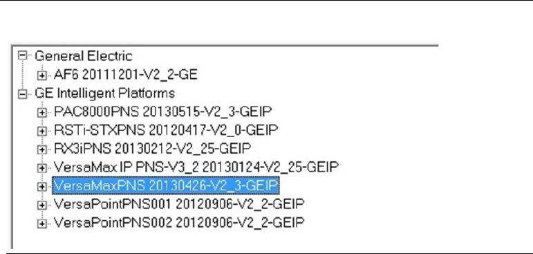
ii. Select the desired device from the Device Catalog.
Figure 5: Select Device from the PMC Catalog
Be sure to select a PNS node that has V2_3 in its name. (A GSDML file of version 2.3 or
higher is required in order to configure the device to be redundantly controlled.)
iii. Because the device supports controller redundancy, PME will
automatically set the device’s Redundancy Mode parameter to HSB CPU
Redundancy.
iv. PME will assign a default name to the device. Be sure to change the
device’s name to match the name you assigned to it during step 9).
v. Add all appropriate I/O carriers (VersaMax only) and I/O modules to the
device’s configuration and set all of the configuration parameters to
appropriate values. For more information about configuring the PNS,
refer to the associated user manual:
▪ VersaMax PROFINET Scanner Manual, GFK-2721A
▪ RX3i PROFINET Scanner Manual, GFK-2737
▪ CEP PROFINET Scanner Manual, GFK-2883
Note: As you assign reference addresses to your redundantly controlled devices, PME
will automatically expand the Primary CPU’s input transfer list to include all
redundantly controlled PROFINET inputs. PME will also automatically expand the
Primary CPU’s output transfer list to include all redundantly controlled PROFINET
outputs.
i. For rack-mounted systems only: Add, replace, and/or move additional RX3i rack
modules to the ‘Hardware Configuration [Primary]’ HWC as needed. Examples of
these modules include power supplies and Ethernet modules. For each Ethernet
PACSystems™ RX3i Hot Standby CPU Redundancy User Manual Section 2
GFK-2308W May 2021
RX3i Hot Standby Redundancy Quick Start with PROFINET I/O 18
module, assign a unique IP address. For CPUs that have no rack-mounted hardware,
make all similar adjustments before proceeding to the next step.
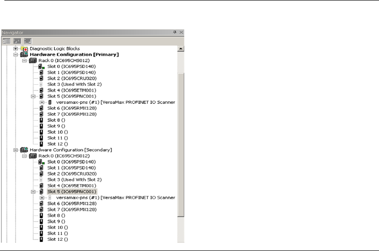
j. Now that you have finished populating the Hardware Configuration of the Primary
CPU, right-click on the ‘Hardware Configuration [Primary]’ node, select
Redundancy, and select Mirror to Secondary Hardware Configuration.
This operation will copy the ‘Hardware Configuration [Primary]’ (including the
transfer lists, the PNC, and the redundantly controlled PROFINET devices) to the
‘Hardware Configuration [Secondary]’ HWC. The result should look similar to Figure
6. (In this diagram, only one PNS is shown.)
Figure 6: RX3i Hot Standby Redundancy Quick Start with PROFINET I/O
m) Select the PNC underneath the ‘Hardware Configuration [Secondary]’ HWC.
i. Assign a unique name and IP address to this PNC.
ii. Set this PNC’s Media Redundancy parameter to Client.
iii. In order to fail-over to the Backup PLC if both PNC MRP ports are disconnected,
set the ports used for MRP to Network Port # Critical = True (the 2nd MRP port will
auto-select when the first MRP port is selected).
n) For each Ethernet module in the Secondary Hardware Configuration, assign a unique IP
address.
8) Add logic to the target.
Note: This is the sequence for downloading configurations into a new redundancy
system. Both units are initially stopped with no configuration.

PACSystems™ RX3i Hot Standby CPU Redundancy User Manual Section 2
GFK-2308W May 2021
RX3i Hot Standby Redundancy Quick Start with PROFINET I/O 19
9) Download the Hardware Configuration and Logic to the Primary controller.
a) Right-click on the ‘Hardware Configuration [Primary]’ node and select Set as
Selected HWC. (If this menu item is greyed out, then you already have the
Primary HWC selected.)
b) Click on the target node in PME’s Navigator. In the Property Inspector, set
the Physical Port and IP Address so that they correspond to your Primary
controller.
c) Select Target -> Go Online.
d) Select Target -> Download <target name> to controller
e) Select Hardware Configuration and Logic and click OK.
i. Expect the Primary CPU to log a Redundancy link communication failure
Controller fault for each RMX module
6
. For example:
0.6
Redundancy link communication failure
0.7
Redundancy link communication failure
ii. Confirm that the Primary CPU did not record any Loss of Device faults in
its I/O fault table.
f) Select Target -> Go Offline.
10) Download the Hardware Configuration and Logic to the Secondary controller.
a. Right-click on the ‘Hardware Configuration [Secondary]’ node and select Set
as Selected HWC.
b. Click on the target node in PME’s Navigator. In the Property Inspector, set
the Physical Port and IP Address so that they correspond to your Secondary
controller.
c. Select Target -> Go Online.
d. Select Target -> Download <target name> to controller.
e. Select Hardware Configuration and Logic and click OK.
i. For both RMX modules in both units, confirm that the LINK OK LEDs
are ON. (This might take a few seconds.)
ii. Confirm that the Secondary CPU did not record any Loss of Device
faults in its I/O fault table.
6
Dual RMX configuration is no longer required for the CPE330 with PME SIM14 or later and firmware 9.75 or
later. This also applies to the CPE330 when it is in CRU320 compatibility mode,

PACSystems™ RX3i Hot Standby CPU Redundancy User Manual Section 2
GFK-2308W May 2021
RX3i Hot Standby Redundancy Quick Start with PROFINET I/O 20
f. Select Target -> Go Offline.
11) You may now connect the last link of the PROFINET network (left open in step 4) above)
to complete the ring.
12) Connect PME to the Primary CPU, and put the Primary CPU into Run mode.
Expect the Primary CPU to log a Primary CPU is Active; no Backup Unit available Controller
fault. For example:
0.2
Primary CPU is Active; no Backup Unit available
13) Connect PME to the Secondary CPU, and put the Secondary CPU into Run mode. Expect
the Primary CPU to log a Primary CPU is Active and Secondary CPU is Backup Controller
fault. For example:
0.2
Primary CPU is Active and Secondary CPU is Backup
This quick start procedure demonstrates the setup and configuration of a basic RX3i
Hot Standby CPU Redundancy system that uses PROFINET I/O. This basic setup can
be used to learn about other Redundancy features such as Role Switching, Transfer
Lists, Non-Synchronized Active Unit (NSAU), and Redundant IP which are described in
the latter chapters of this manual.
PACSystems™ RX3i Hot Standby CPU Redundancy User Manual Section 3
GFK-2308W May 2021
RX3i Hot Standby Redundancy Quick Start with Ethernet I/O 21
Section 3: RX3i Hot Standby Redundancy
Quick Start with Ethernet I/O
This chapter provides an overview of the steps needed to configure and operate a
basic RX3i Hot Standby (HSB) CPU Redundancy system with one Ethernet Remote I/O
(ENIU) using an ENIU Machine Edition template.
A template set is a zip file containing pre-configured Ethernet NIU (ENIU) and
controller projects for PAC Machine Edition or PAC Process Control. The template set
simplifies the configuration of the controllers and ENIUs because the Ethernet Global
Data exchanges are already set up, along with a default number of inputs and
outputs for the system. If the default values are used, the only steps needed to
implement I/O communication are assigning Ethernet IP addresses, configuring I/O
modules and storing to the controllers and ENIUs. The templates may be
downloaded from PAC Machine Edition. Refer to the PACSystems RX3i Ethernet
Network Interface Unit User’s Manual, GFK-2439.
Note: The Primary and Secondary CPUs in a redundancy system must be of the same
type. An RX3i controller cannot function as a redundant pair.
1) Set up two identical controller systems. One system will be designated as Primary and the
other will be designated as Secondary.
a. For rack-mounted systems, install one Redundant CPU, one or two RMX modules
and three Ethernet (ETM001) modules each into each system. Install the ETM
modules in the slot locations indicated by Table 3 for RX3i.
b. For CPE330, you may not replace the rack-mounted ETM modules with
embedded Ethernet: install rack-mounted ETM modules per Table 3.
c. ENIU templates for embedded PROFINET Controllers are not available at time of
publication, so this feature cannot be used with CPE400, CPL410 or with the
embedded PROFINET Controller of a CPE330 at this time.
2) (Applies to CRU320 only.) With the CPU battery disconnected, apply power to the racks.
When power is applied to the RMX module an internal loopback test occurs; the OWN
DATA and SIGNAL DETECT indicators turn on briefly during this test. When the RMX
module and the CPU are powered up and functioning properly, the RMX module’s OK
indicator is on.
3) (Applies to CRU320 only.) Connect a battery to each redundant CPU.
The redundant CPUs support Error checking and correction (ECC) memory, which must
be initialized at least one time with the battery disconnected. Once ECC memory is
initialized, the CPU can be power cycled with the battery connected.
4) Download and unzip the appropriate template set for your system.

PACSystems™ RX3i Hot Standby CPU Redundancy User Manual Section 3
GFK-2308W May 2021
RX3i Hot Standby Redundancy Quick Start with Ethernet I/O 22
Templates for redundancy systems are available from the Support website. On the
website, select Downloads, then select the Developer Files category.
For a list of available template sets, refer to the PACSystems RX3i Ethernet Network
Interface Unit User’s Manual, GFK-2439. Each template set consists of a Controller
template and an ENIU template.
5) Using the Machine Edition Logic Developer software, restore the Controller project from
the appropriate ENIU template set.
6) Open the restored project. Assign IP addresses to all the Ethernet LANs.
In assigning IP addresses, consider the following functions:
Table 3: RX3i Rack-mounted Configuration
Ethernet Interface
Function
ETM001 in Slot 6
7
Programmer connection to your computer
Requires a Redundant IP address, which should be the same IP Address
for both the Primary and Secondary rack systems.
ETM001 in Slot 7
Private network, LANA for Ethernet I/O exchanges
ETM001 in Slot 8
Private network, LANB for Ethernet I/O exchanges
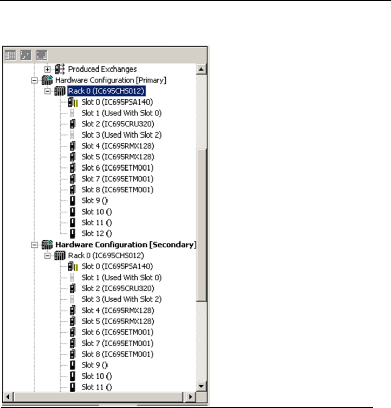
The hardware configuration should appear similar to Figure 7, which shows an RX3i
configuration:
7
ETM001 in Slot 6 may be replaced by the Ethernet port embedded in CPUs such as CPE330.
PACSystems™ RX3i Hot Standby CPU Redundancy User Manual Section 3
GFK-2308W May 2021
RX3i Hot Standby Redundancy Quick Start with Ethernet I/O 23
Figure 7: RX3i Hardware Configuration Provided by an ENIU Controller Template
Project
7) Use fiber-optic cable to connect each RMX module in the Primary Rack to the
corresponding RMX module in the Secondary Rack (the module in the same Slot
number) as described in Figure 8.
Using an LC-compatible fiber-optic cable, connect the TX connector on one RMX module to the
RX connector of the other RMX module, and vice-versa (refer to Figure 8.) When the fiber-optic
transceiver detects a signal on the network, the SIGNAL DETECT indicator will be on.

PACSystems™ RX3i Hot Standby CPU Redundancy User Manual Section 3
GFK-2308W May 2021
RX3i Hot Standby Redundancy Quick Start with Ethernet I/O 24
Figure 8: Fiber Optic Cable Connections for RMX Modules
Note: Ensure that the cable type matches the module type, such that, single-mode cable is
used for single mode modules and multimode cable is used for multimode modules.
8) In PAC Machine Edition, close the Controller project and restore the ENIU project from an
ENIU template set:
Open the project and on target ENIU_01 open the Hardware Configuration. Set the IP
addresses of the ETM001 modules, taking into consideration that the ETM001 in Slot 4
of the ENIU rack will be on a private network called LANA (connected to LANA of the
Redundancy CPUs) and the ETM001 in Slot 5 will be on a private network called LANB
(connected to LANB of the Redundant CPUs).
The hardware configuration should appear similar to Figure 9, which shows an RX3i
configuration.

PACSystems™ RX3i Hot Standby CPU Redundancy User Manual Section 3
GFK-2308W May 2021
RX3i Hot Standby Redundancy Quick Start with Ethernet I/O 25
Figure 9: ENIU Hardware Configuration Provided by an ENIU Template Project
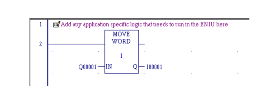
9) Add I/O loopback logic to confirm data transfer between ENIU and Redundant CPUs
Under the Logic node in PAC Machine Edition, open the Program Block
Local_User_Logic. Add the logic shown in Figure 10 to loop outputs %Q1-%Q16 back
to inputs %I1-%I16.
PACSystems™ RX3i Hot Standby CPU Redundancy User Manual Section 3
GFK-2308W May 2021
RX3i Hot Standby Redundancy Quick Start with Ethernet I/O 26
Figure 10: Add Ladder Logic for ENIU
10) (Applies to rack-mounted systems only.) Install a Power supply, RX3i ENIU
(IC695NIU001) and two ETM001 modules into an RX3i backplane as shown the
hardware configuration in step 6). Apply power to the system.
11) Connect your PC to the ENIU via a Serial cable from the ENIU module’s COM1 or
COM2 port to one of your PC’s COM ports or install an additional ETM001 module to
the ENIU rack to provide connectivity via Ethernet. With the template folder open in
PAC Machine Edition, connect to the ENIU either by a COM port or by Ethernet.
Store the ENIU_01 application to the ENIU and put the ENIU into run mode.
12) Connect Ethernet cables between the Redundant CPUs and the ENIU rack system.
RX3i Connections
LANA: Connect one Ethernet cable from ETM001 in Primary Rack Slot 7 to
ETM001 in ENIU Rack Slot 4. Connect one Ethernet cable from ETM001 in Primary
Rack Slot 8 to ETM001 in ENIU Rack Slot 5.
LANB: Connect one Ethernet cable from ETM001 in Secondary Rack Slot 7 to
ETM001 in ENIU Rack Slot 4. Connect one Ethernet cable from ETM001 in
Secondary Rack Slot 8 to ETM001 in ENIU Rack Slot 5.
13) Connect Ethernet cables between an Ethernet switch connected to your PC and the
ETM001 modules assigned as Programmer connections in both the Primary and
Secondary CPU systems.
14) Close _10ENIU_CRU_DLDI_ENIU_1_10 project in PAC Machine Edition and again open
project _10ENIU_CRU_DLDI_Controller
a) Right-click on the Primary Hardware Configuration node and select Set as
Selected HWC. Connect to the Secondary CPU, store the application and put the
CPU in run mode.
b) Disconnect from the Primary CPU. Right-click on the Secondary Hardware
Configuration node and select Set as Selected HWC. Connect to the Secondary
CPU, store the application and put the CPU in run mode.
PACSystems™ RX3i Hot Standby CPU Redundancy User Manual Section 3
GFK-2308W May 2021
RX3i Hot Standby Redundancy Quick Start with Ethernet I/O 27
c) Right-click on the Reference View Tables node and select New. Double-click the
RefViewTable10 node just created. In the address box, enter %Q1. In the next
address box below %Q00001, enter %l1. Right-click in the Values area just to the
left of the Address boxes and select Format View Table. Check the box labeled
Apply to Whole Table, select Word for the Display Type, select Hex for the Display
Format and click Ok. Enter values into the %Q00001 values area and notice that
the same values are displayed at %l00001 because of the loopback logic in the
ENIU.
NOTE: For details on configuring an RX3i Genius dual bus redundancy system,
refer to Appendix A.
This quick start guide procedure demonstrates setup of a PACSystems
Redundancy Controller pair controlling one ENIU remote IO station. This basic
setup can be used to learn about other CPE Redundancy features such as Role
Switching, Transfer Lists Non-Synchronized Active Unit (NSAU) and Redundant
IP. For details on the operation of CPU Redundancy systems, refer to the other
chapters in this manual.
PACSystems™ RX3i Hot Standby CPU Redundancy User Manual Section 4
GFK-2308W May 2021
System Configuration 28
Section 4: System Configuration
This chapter describes the hardware components for a Hot Standby CPU Redundancy
system and describes system configurations for the basic redundancy schemes
supported by PACSystems controllers.
For installation instructions, refer to
• PACSystems RX3i System Manual, GFK-2314.
4.1 Components of a Hot Standby Redundancy
System
• Core Systems
• Redundant CPU
• Redundancy Memory Xchange modules
• Redundant I/O Systems
4.1.1 Core Systems
RX3i Systems with Racks
In an RX3i redundancy system where the CPU is mounted in an RX3i rack, an RX3i
(IC695CHS0xx) Universal Backplane must be used as the CPU rack. This rack is
referred to as Rack 0. For specific backplane versions required, refer to the Important
Product Information document provided with your RX3i CPU.
Any RX3i expansion rack or any Series 90-30 expansion rack that is supported by RX3i
can be used in a rack-mounted RX3i redundancy system.
RX3i Systems without Racks
CPE400 and CPL410 are RX3i CPUs which cannot be installed in an RX3i rack. They
therefore do not support RMX modules, rack-mounted PNC modules or rack-
mounted Ethernet modules. Sections of this manual will therefore specify how
CPE400/CPL410 systems may be used in Redundancy applications. While the system
rack is physically absent in CPE400/CPL410 configurations, the CPE400/CPL410 itself
is able to provide all the equivalent functionality via its embedded PROFINET
controller and embedded Ethernet networks. All I/O in this type of system is
PROFINET I/O, since no rack-mounted I/O is permitted.
CPE400/CPL410 do not support Hot Standby Redundancy for Ethernet IO. Such
systems require an ETM001, which the CPE400/CPL410 do not support.
CPE400/CPL410 do not support expansion racks.
PACSystems™ RX3i Hot Standby CPU Redundancy User Manual Section 4
GFK-2308W May 2021
System Configuration 29
4.1.2 Redundant CPU Modules
To use the features described in this manual, RX3i Redundant CPUs (except CPE400
and CPL410, which are not rack-mounted CPUs) must be installed in any slot in rack
0.
Note: A given feature may not be implemented on all PACSystems CPUs. To
determine whether a feature is available on a given CPU model and firmware version,
please refer to the Important Product Information (IPI) document provided with the
CPU.
The CPU provides configurable reference memory limits for %AI (Analog Input), %AQ
(Analog Output), %R (Register), and %W (bulk memory area) reference memory, as
well as symbolic discrete reference memory and symbolic non-discrete reference
memory. For additional CPU features and performance specifications, refer to the
PACSystems RX3i and RSTi-EP CPU Reference Manual, GFK-2222.
Operation of the CPUs can be controlled by the three-position RUN/STOP switch or
remotely by an attached programmer and programming software. Program and
configuration data can be locked through software passwords. The LEDs on the front
of the module indicate CPU and Ethernet interface status.
• Redundant IP address
• Production of selected EGD exchanges in Backup mode
• Up to 255 Ethernet Global Data (EGD) exchanges with up to 100 variables
per exchange.
• EGD upload and selective consumption of EGD exchanges.
• Upload and download of an Advanced User Parameter (AUP) file, which
contains user customizations to internal Ethernet operating parameters.
• Run mode store of EGD (PACSystems releases 5.5 and later), which allows
you to add, delete or modify EGD exchanges without stopping the controller.
For details on using this feature, refer to the PACSystems RX3i and RSTi-EP
TCP/IP Ethernet Communications User Manual, GFK-2224.
• Redundant CPUs Compared to Standard PACSystems CPUs
• The following features are not available:
• I/O and module interrupts: This includes the single edge triggered interrupts
from the discrete input modules, the high alarm and low alarm interrupts
from the analog input modules, and interrupts from VME modules. A
program that declares I/O Interrupt triggers cannot be stored to a
Redundant CPU.
• Interrupt Blocks (I/O, timed, module): Logic that contains interrupt blocks
cannot be stored to a Redundant CPU.
• Stop I/O Scan mode: If an attempt is made to place a Redundant CPU in this
mode, the controller will reject the selection and return an error.
• #OVR_PRE %S reference, which indicates whether one or more overrides are
active, is not supported in a Redundant CPU, and should not be used.
• RX3i Redundant CPUs do not support the PACMotion module
(IC695PMM335).

PACSystems™ RX3i Hot Standby CPU Redundancy User Manual Section 4
GFK-2308W May 2021
System Configuration 30
• The following features operate differently in redundant CPUs than they do in
standard PACSystems CPUs:
• Error checking and correction (ECC) is enabled.
8
• RUN/DISABLED mode. This is explained in Section 6:, Operation.
• User-configurable fault actions are not used when the CPUs are
synchronized.
• STOP to RUN mode transition. For details, refer to Section 6.2, Synchronizing
Redundant CPUs.
• Background Window Timer (in Normal Sweep mode) default is 5ms. It is
highly recommended that the Background Window Timer be set to the same
value for both CPUs making up a redundancy pair.
• By default, Ethernet Global Data (EGD) is produced only by the Active unit.
The Backup unit can produce individual EGD exchanges that are configured
for production in Backup mode.
Also, be aware that instance data associated with IEC transitionals (PTCOIL, NTCOIL,
PTCON, and NTCON) is not synchronized between the two CPUs. For details, refer to
Section 6.6, Data Transfer.
Using the Redundant CPU for Simplex Operation
The Redundant CPU can be used for both redundant and simplex (non-redundant)
applications. The functionality and performance of a Redundant CPU configured for
simplex operation is the same as for a unit that is configured for redundant operation
with no Backup available. This includes the redundancy informational messages such
as those generated when a unit goes to Run mode.
8
Exception: CPL410, CPE400 and CPE330 always operate with Error checking and Correction (ECC) enabled, even in non-Redundant
applications.

PACSystems™ RX3i Hot Standby CPU Redundancy User Manual Section 4
GFK-2308W May 2021
System Configuration 31
4.1.3 Redundancy Memory Xchange Modules
Rack-mounted redundancy systems use a pair of RMX modules to provide a path for
transferring data between the two redundant CPUs. A complete communications
path consists of one RMX in the Primary CPU rack, one RMX in the Secondary CPU
rack, and two high-speed fiber-optic cables connecting them to each other. This
must be a two-node ring: no other reflective memory nodes are allowed to be part of
this fiber-optic network.
Note that CPE330 is required to use RMX modules in hot standby redundancy
applications, just like any other rack-mounted RX3i system. Its high-speed LANs
cannot be used as a substitute redundancy link.
When using PROFINET, Ethernet NIUs or Genius for the redundantly controlled I/O, it
is strongly recommended that two redundancy links (for a total of four RMX
modules) be configured and installed.
RMX modules must be installed in the main rack (rack 0).
The RMX module has a toggle switch that can be used to manually request a role
switch. Eight LEDs, described in the following table, provide indication of module
status.
Note: The RX3i RMX128/RMX228 module supports hot insertion and removal.
However, the redundancy communication link associated with a hot swapped RMX
module will not be restored automatically. The LINK OK indicator on both RMX
modules in the link will be OFF. To restore the link, refer to Section 7.5, Online Repair
and System Upgrade.
RMX LEDs
Table 4: RMX LED Definitions
LED Label
Description
OK
ON indicates the module is functioning properly.
LINK OK
When used as a redundancy link, ON indicates the link is
functioning properly.
LOCAL READY
ON indicates the local unit is ready.
LOCAL ACTIVE
ON indicates the local unit is Active.
REMOTE READY
ON indicates the remote unit is ready.
REMOTE ACTIVE
ON indicates the remote unit is Active.
OWN DATA
ON indicates the module has received its own data packet from
the network at least once.
SIGNAL DETECT SIG
DETECT
ON indicates the receiver is detecting a fiber-optic signal.
PACSystems™ RX3i Hot Standby CPU Redundancy User Manual Section 4
GFK-2308W May 2021
System Configuration 32
Certain RMX LEDs (refer to Section 6.3) are also reflected in the %S status bits. This
allows the application software to read the active/ready status of the local and
remote CPUs.
4.1.4 Redundant I/O Systems
PROFINET
Applications that require a highly available control system that survives a single point
of failure in the controllers and a single point of failure in the I/O network can
leverage PROFINET I/O. This solution allows you to interface the RX3i Redundant CPU
to remote VersaMax I/O across an Ethernet network. RX3i PROFINET Redundancy is
an evolution of the PACSystems Hot Standby ENIU solution to an industry-standard
I/O protocol.
For sample Hot Standby CPU Redundancy systems that use PROFINET I/O, refer to
Section 4.2, CPU Redundancy Using PROFINET I/O.
Ethernet Network Interface Unit (ENIU)
CPU-based ENIU modules can be used to interface the RX3i Redundant CPU to
remote I/O stations through Ethernet LANs. These devices, which include
IC695NIU001 and IC693NIU004, make it possible to use PACSystems RX3i remotely
on an Ethernet network.
An identical set of EGD exchange definitions is downloaded to both the Primary and
Secondary controllers. An ENIU can consume EGD exchanges from two controllers
simultaneously. However, when used with redundant controllers, the ENIU
automatically switches to the standby controller if the Active controller becomes
unavailable.
For sample redundancy systems using EGD, refer to Section 4.2, CPU Redundancy
Using PROFINET I/O. For details on EGD operation in a redundancy system, refer to
Section 6.17, Ethernet Global Data in an HSB Redundancy System. For details on the
operation of ENIUs, refer to the PACSystems RX3i Ethernet Network Interface Unit User’s
Manual, GFK-2439.
Genius Bus Controller and Genius Devices
The Genius Bus Controller interfaces the Redundant CPU to a Genius I/O bus. The bus
controller scans Genius devices asynchronously and exchanges I/O data with the CPU.
An HSB CPU Redundancy system can have multiple Genius I/O bus networks. Any
Genius device can be placed on the bus (Genius blocks, Field Control, Remote I/O
Scanner, VersaMax I/O, and so forth). The Genius outputs are determined by the
Active unit. The Genius Bus Controller installed in the Primary CPU has a Serial Bus
Address of 31; the Genius Bus Controller installed in the Secondary CPU has a Serial
Bus Address of 30. For sample redundancy systems using Genius I/O, refer to Section
4.4.2, Basic CPU Redundancy Using Genius I/O.
Note: For RX3i systems with Dual Genius Buses, only VersaMax I/O Genius Network
Interface Units (GNIU) are supported. For non-Dual Genius Buses, any Genius device
PACSystems™ RX3i Hot Standby CPU Redundancy User Manual Section 4
GFK-2308W May 2021
System Configuration 33
can be placed on the bus (Genius blocks, Field Control, Remote I/O Scanner,
VersaMax I/O, and such).
OPC UA
The OPC UA allows monitoring and control information to be collected for HMI,
automation, aggregation, and/or historical tracking. This solution allows non-transparent
redundancy for clients which support it. Enabling redundancy and OPC UA is sufficient to
enable it on the CPU pair.
Note: Both PME 9.8 SIM 5 and PLC Firmware 10.10 or greater versions are required.
Note:
In a non-transparently redundant pair configuration, the client is responsible for
connecting to the two systems and swapping in the event of a failure.
4.1.5 Local I/O
Local I/O can be included in either unit; however, it is not part of the redundant I/O
system. A failure in the Local I/O system will affect the unit as described in the
PACSystems RX3i and RSTi-EP CPU Reference Manual, GFK-2222.
4.2 CPU Redundancy Using PROFINET I/O
This section discusses sample system architectures using PROFINET I/O with Hot
Standby CPU Redundancy. These sample system architectures support both general
communications (such as a programmer connection) and remote I/O data transfers.
Remote I/O data transfers use PROFINET across an Ethernet connection to the
remote devices.
If you need I/O network redundancy, you must use an MRP ring topology. If you do
not need I/O network redundancy, you can use a star network topology. Additional
details on these network architectures are presented below.
A CPU Redundancy system can also contain simplex (non-redundantly controlled) IO
devices that are configured and controlled at only one CPU unit.
4.2.1 Configuration Considerations
Redundancy Links
When you use redundantly controlled PROFINET I/O, you are required to configure a
minimum of one redundancy link. A failed redundancy link should be repaired as
soon as possible.
PACSystems™ RX3i Hot Standby CPU Redundancy User Manual Section 4
GFK-2308W May 2021
System Configuration 34
Input Data Validation
To determine the health of PROFINET Inputs, the logic application must use the I/O
Point Faults associated with those inputs. To use point faults, they must be enabled in
Hardware Configuration (HWC) on the Memory parameters tab of the CPU.
The logic application may use the All Devices Connected PNC module status bit to
determine connectivity to PROFINET I/O-Devices. However, the logic application
must not use the All Devices Connected status bit to determine the health of Input
data from a PROFINET I/O-Device because this bit is not synchronized to Input data
delivery.
For additional information on input data validation, refer to the PACSystems RX3i and
RSTi-EP CPU Reference Manual, GFK-2222.
Network Size
A Redundant CPU can control a maximum of 255 PROFINET I/O Devices.
The PAC Machine Edition allows a maximum of 128 simplex or redundant nodes to be
connected together in a Media Redundancy Protocol (MRP) ring topology. One of the
nodes must operate as the Media Redundancy Manager. All the other nodes that
participate in the ring must operate as Media Redundancy Clients. If the PNC is the
MRP Ring Manager, only 64 nodes are supported in an MRP Ring.
An individual PNC can control a maximum of 128 I/O devices.
For more information, refer to Section 5: Configuration Requirements.
4.2.2 Configuration Overview
For both controllers to be able to connect to a redundantly controlled PROFINET I/O
Device and control that device’s I/O, both controllers must have identical copies of
the hardware configuration for that device. PAC Machine Edition does not permit a
redundantly controlled I/O Device to be configured in a standalone (non-Dual HWC)
target.
Critical Network Ports
To force a CPU redundancy role-switch to occur when an I/O network connection is
lost, configure the desired PNC module’s port as a Critical Network Port. It is
permissible to configure more than one port as critical. When all of the Critical
Network Port connections are lost, a diagnostic fault is logged by the PROFINET
Controller with the CPU placed into Stop/Fault mode, which invokes the CPU
redundancy role-switch if the PROFINET Controller is controlling redundant devices.
Critical Network Ports are described in the PACSystems RX3i PROFINET Controller
Manual, GFK-2571, Chapter 3, Configuration - PROFINET Controller Parameters (Settings
Tab).
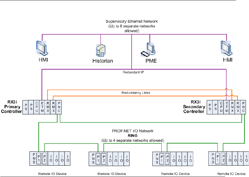
PACSystems™ RX3i Hot Standby CPU Redundancy User Manual Section 4
GFK-2308W May 2021
System Configuration 35
4.2.3 PROFINET Network Architectures
MRP Ring Topology (Strongly Recommended)
To ensure greater reliability and eliminate your I/O network as a single point of
failure, the PROFINET devices should be connected together in a ring topology as
shown below. This ring topology uses the PROFINET Media Redundancy Protocol
(MRP), as described in the PACSystems RX3i PROFINET Controller Manual, GFK-2571,
Chapter 6, Redundant Media.
Even though a Hot Standby CPU Redundancy system uses PROFINET I/O Controllers
in both the Primary and Secondary CPUs, only one I/O Controller in the entire I/O
network can operate as the Media Redundancy Manager (MRM). All other PROFINET
I/O Controllers in the same I/O network must be configured as Media Redundancy
Clients.
Figure 11: MRP Ring Topology
Note: The HMIs and the Historian shown in Figure 11 are optional.
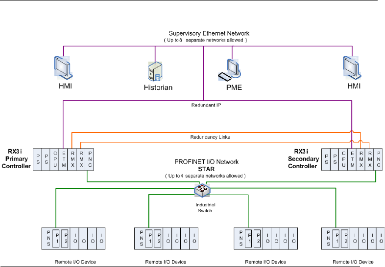
PACSystems™ RX3i Hot Standby CPU Redundancy User Manual Section 4
GFK-2308W May 2021
System Configuration 36
Star Topology
If eliminating your network as a single point of failure is not required, the PROFINET
devices can be interconnected in a star topology as shown below.
Note: To eliminate single point failures within your network infrastructure, the MRP
ring topology is recommended.
Figure 12: MRP Star Topology
Note: The HMIs and the Historian shown in Figure 12 are optional.

PACSystems™ RX3i Hot Standby CPU Redundancy User Manual Section 4
GFK-2308W May 2021
System Configuration 37
4.3 CPU Redundancy Using Ethernet NIU Remote
I/O
This section discusses sample system architectures using Ethernet remote I/O
9
with
CPU hot standby redundancy systems.
These sample system architectures support both general communications (such as a
programmer connection) and remote I/O data transfers. Remote I/O data transfers use
EGD to and from the ENIUs.
For general communication in a hot-standby redundancy system, the Redundant IP
feature must be enabled for the Ethernet interface. In general communication, only
the Active CPU produces EGD exchanges. When a redundancy role switch occurs, the
Backup CPU becomes Active and begins producing EGD. The formerly Active CPU
switches to Backup and stops producing EGD.
For remote I/O operation, the Active and Backup CPUs simultaneously process
remote I/O EGD exchanges for each ENIU. For architectures using redundant remote
I/O LANs, the CPUs process separate remote I/O EGD exchanges on each LAN. All EGD
exchanges that can simultaneously occur on a network must have unique Exchange
IDs. Hence remote I/O exchanges that are produced by both the Primary and
Secondary CPUs must have different Exchange ID values. Remote I/O EGD production
continues across CPU role switches. The application logic in the ENIU selects which
EGD remote I/O output exchanges to consume for controlling outputs.
If the Active controller transitions to Run I/O Disabled mode, it continues to receive
inputs from the ENIU. However, the ENIU no longer receives outputs from the
controller. The ENIU’s status words can be monitored to detect communication
activity. For details on the status words, refer to the PACSystems RX3i Ethernet Network
Interface Unit User’s Manual, GFK-2439.
Note: These architectures are based on the template sets provided for use with PAC
Machine Edition and PAC Process Systems programmers. The templates are set up
with coordinated references and coordinated parameters for 10, 20, or 24 ENIUs. For
systems with other numbers of ENIUs, select the template with the next larger
number of ENIUs and delete the extra ENIUs.
4.3.1 Dual Controller, Single LAN Systems
The following template sets
9
are available to configure these architectures.
Architecture
Templates for PAC
Machine Edition
Templates for PAC
Process Systems
Dual RX3i CPU Controllers, Single
LAN
10 ENIUs,
20 ENIUs
10 ENIUs,
20 ENIUs
9
For details about the ENIU configuration and operation and use of the ENIU templates, refer to the
PACSystems RX3i Ethernet Network Interface Unit User’s Manual, GFK-2439.
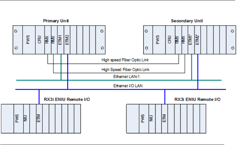
PACSystems™ RX3i Hot Standby CPU Redundancy User Manual Section 4
GFK-2308W May 2021
System Configuration 38
RX3i Dual Controller, Single LAN System
In this architecture, general communications and remote I/O data transfer coexist on
separate Ethernet LANs and thus do not contend for network bandwidth. This keeps
remote I/O performance from being degraded.
The Redundant IP feature is enabled for the Ethernet interface in both controllers to
permit general communications. Any EGD exchanges used for general CPU
communications are not configured as Produce in Backup Mode.
The produced EGD exchanges that are used for remote I/O data transfer are
configured as Produce in Backup Mode so that they will be produced in both Active and
Backup mode.
For easier configuration, each EGD exchange marked as Produce in Backup is
configured with the Exchange ID value used by the Primary CPU. The Programmer
automatically generates a unique Exchange ID value for the Secondary CPU by adding
the configured “Secondary Produced Exchange Offset” value to the configured
Exchange ID value. For details on the exchange offset, refer to Section 6.17.1,
Ethernet Global Data Production.
Figure 13: RX3i System with Dual Controllers, Single LAN
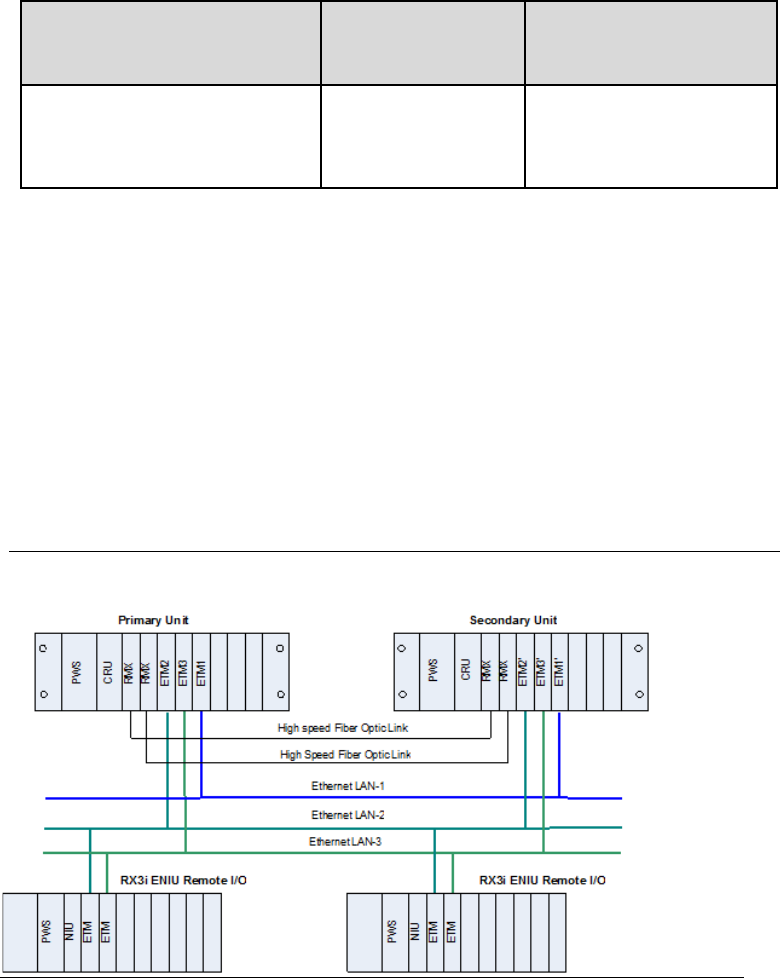
PACSystems™ RX3i Hot Standby CPU Redundancy User Manual Section 4
GFK-2308W May 2021
System Configuration 39
4.3.2 Dual Controller, Dual LAN Systems
The following template sets are available to configure these architectures.
Table 5: Template Sets for PAC Architectures
Architecture
Templates for PAC
Machine Edition
Templates for PAC Process
Systems
Dual RX3i CPU Controllers, Dual
LAN
10 ENIUs,
20 ENIUs
10 ENIUs,
20 ENIUs
RX3i Dual Controller, Dual LAN System
In this system architecture, the remote I/O stations each have two Ethernet modules
to provide the stations with redundant LAN connections to the controllers. LAN3 acts
as a backup to LAN2.
The Redundant IP feature is enabled for the Ethernet interfaces on LAN1 because it
handles general communications. EGD exchanges used for general CPU
communications are not produced in Backup mode.
Each controller uses a separate Ethernet interface for communication on each
remote I/O LAN (one for LAN2 and another for LAN3). The remote I/O EGD exchanges
are configured on the Ethernet interfaces for the appropriate LAN.
Figure 14: RX3i System with Dual Controllers, Dual LANs
PACSystems™ RX3i Hot Standby CPU Redundancy User Manual Section 4
GFK-2308W May 2021
System Configuration 40
4.4 Genius Hot Standby Operation
In a Genius Hot Standby CPU redundancy system, the Genius outputs are controlled
by only one unit (the Active unit). The inputs are shared between both units. One unit
is the Primary CPU and the other is the Secondary CPU. The Primary CPU controls all
externally redundant Genius Bus Controllers at SBA 31; the Secondary CPU controls
all externally redundant Genius Bus Controllers at SBA 30.
The Genius output devices are normally configured for Genius Hot Standby
redundant operation. With this configuration, the devices choose between outputs
from the Genius Bus Controller at SBA 31 and the Genius Bus Controller at SBA 30. If
outputs from both Genius Bus Controllers are available, the devices will use outputs
from SBA 31. If there are no outputs from SBA 31 for three consecutive Genius I/O
bus scans, the devices will use the outputs from SBA 30. If outputs are not available
from either SBA 31 or 30, the outputs go to their configured default (OFF or hold last
state).
4.4.1 Genius Output Control
In a Genius Hot Standby CPU Redundancy system, the Active unit determines the
values of the Genius outputs.
Both the Primary and Secondary CPUs send outputs regardless of which one is Active.
The user is responsible for ensuring that all redundant Genius outputs are included in
the output data transfer. Because the same output values will then be sent to the
GBCs in both units, the devices will receive the same output values from SBA 31 and
SBA 30. There is no data interruption on switchover because both units are always
sending Genius outputs.
Note: In an RX3i CPU Redundancy system, when a GBC is configured as Redundant
Controller – External, all its outputs are redundant.
4.4.2 Basic CPU Redundancy Using Genius I/O
Hot Standby CPU Redundancy supports two types of bus schemes for the Genius
networks:
• Single bus networks
• Dual bus networks
Note: For RX3i systems, Dual Genius Bus support is provided by a set of logic blocks.
Templates for RX3i Dual Genius Bus support can be downloaded from the Support
web site. For details on using these templates, refer to Appendix A, RX3i Dual Genius
Bus Overview and the PACSystems RX3i Dual Genius Bus Quick Start Guide, which is
provided with the RX3i Dual Bus Templates.
PACSystems CPU Redundancy implements a floating master algorithm. If an
application requires a preferred master algorithm, refer to Section 6.7.4,
Implementing Preferred Master Using SVC_REQ 26.
PACSystems™ RX3i Hot Standby CPU Redundancy User Manual Section 4
GFK-2308W May 2021
System Configuration 41
Redundant Controllers, Single Genius Bus Networks
This type of network uses a single bus with one Genius Bus Controller in each
controller.
The single bus setup is suitable if the application does not require redundant I/O
buses. When using single-bus Genius networks in a Hot Standby CPU Redundancy
system, one Genius Bus Controller for the bus must be located in the Primary CPU
system and one in the Secondary CPU system. There can be multiple Genius buses in
each system. The bus controllers controlled by the Primary CPU are assigned Serial
Bus Address 31. The bus controllers controlled by the Secondary CPU are assigned
Serial Bus Address 30.
Genius output devices will use outputs from Serial Bus Address 31 in preference to
outputs from Serial Bus Address 30. Outputs are determined by the Active unit,
regardless of which bus controller provides the outputs since all redundant Genius
outputs are transferred from the Active unit to the Backup unit.
Hardware Configuration for RX3i Single Bus Network
For RX3i targets, the hardware configuration for single bus networks is created by
adding a GBC and adding Genius devices to that GBC.
The GBCs must be configured with the following settings.
Redundancy Mode: Redundant Controller - External
SBA: 31 (Primary CPU) or 30 (Secondary CPU)
The Genius devices must be configured for Hot Standby mode. For example, use the
following settings for a Genius block:
• (Hand-Held Monitor) CPU Redundancy = HOT STBY MODE (Hand-Held Monitor) BSM
Present = NO
Dual Genius Bus Networks
This option provides redundancy of both the controller and the I/O bus. This type of
system uses dual buses with bus controllers in each controller. The Dual Bus network
is suitable if the application requires redundancy of the controller and the I/O bus.
A Bus Switching Module (BSM) is required to connect the initial block in the Genius
block daisy chain to the dual bus.
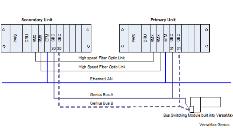
PACSystems™ RX3i Hot Standby CPU Redundancy User Manual Section 4
GFK-2308W May 2021
System Configuration 42
Figure 15: RX3i Redundant Controllers with Dual Genius Bus
When using dual bus Genius networks in a Hot Standby CPU Redundancy system, two
bus controllers for the bus pair must be located in the Primary CPU system and two
more in the Secondary CPU system. There can be multiple dual bus pairs. The bus
controllers in the Primary CPU system are assigned Serial Bus Address 31. The bus
controllers in the Secondary CPU system are assigned Serial Bus Address 30.
Genius output devices will use outputs from Serial Bus Address 31 in preference to
outputs from Serial Bus Address 30. Outputs are determined by the Active unit,
regardless of which bus controller provides the outputs since all redundant Genius
outputs are transferred from the Active unit to the Backup unit.
Any type of Genius device can be connected to the network. Each Genius network
can have up to 30 additional Genius devices connected to it. You may want to reserve
one Serial Bus Address for the Hand-Held Monitor.
As a safety feature, a watchdog timer protects each Genius I/O link. The bus
controller periodically resets this timer. If the timer expires, the bus controller stops
sending outputs. If this happens in a Dual Bus Genius network of a CPU Redundancy
system, the paired GBC in the other unit drives the outputs of the Genius devices. If
the GBC in the other unit is not available, the BSMs switch to the other bus. The cause
of the failure must be remedied to re -establish communications.
Hardware Configuration for RX3i Dual Bus Network
The hardware configuration for this type of network can be created by adding two
GBCs, one for each bus, and adding the Genius devices to both GBCs. refer to the
PACSystems RX3i Dual Genius Bus Quick Start Guide for more information.
The GBCs must be configured with the following settings:

PACSystems™ RX3i Hot Standby CPU Redundancy User Manual Section 4
GFK-2308W May 2021
System Configuration 43
Redundant Mode:
Redundant Controller - External
SBA:
31 (Primary CPU) or 30 (Secondary CPU)
(Programmer) CPU
Redundancy
= HOT Standby
(Programmer) BSM
Present
= YES (Programmer)
BSM
Controller
= YES
Note: Templates for RX3i Dual Bus Genius come with the VersaMax GNIUs already
configured for the correct Genius network settings.
Location of GBCs and Blocks
For fastest switching, all Genius Bus Controllers in the Hot Standby CPU Redundancy
system should be in the main rack. This will cause the Genius Bus Controller to lose
power at the same time that the CPU loses power and allow the Backup unit to gain
full control of the I/O as soon as possible. Each GBC has an output timer that it resets
during every output scan. If the GBC determines that the CPU in its controller has
failed, it will stop sending outputs to its Genius devices. This allows the other GBC to
take control of the I/O.
For single and dual bus Genius networks, the Genius Bus Controllers should be
connected at the same end of the bus, as shown in Figure 14 and Figure 15. In
particular, the GBC of the Secondary CPU should be placed at one end of the bus and
the GBC of the Primary CPU should be connected to the bus such that it is between
the GBC of the Secondary CPU and the Genius devices. No I/O blocks or other devices
should be connected to the bus between the connection nodes of the two bus
controllers.
In the case of dual bus networks, placing the bus controllers and devices in this
manner minimizes the risk of a bus break between the two units. A bus break
between the units could result in only some devices switching buses, and make the
other devices inaccessible to one of the units. It also allows the Primary CPU to
continue to control the I/O in bus failure conditions that might otherwise result in
loss of inputs and unsynchronized control of outputs.
Since the recommended configuration for single and dual bus networks still has the
possibility of a bus breaking between the two CPUs, you may want to program the
application to monitor the status of the buses from the unit configured at the end of
the buses and request a role switch or bus switch (dual bus network only) if loss of bus
is detected.
Duplex Genius Output Mode
Although it is not common, you can configure your Genius I/O system for duplex
mode, meaning that they will receive outputs from both bus controllers 30 and 31
and compare them. Only devices that have discrete outputs can be configured for
Duplex mode.

PACSystems™ RX3i Hot Standby CPU Redundancy User Manual Section 4
GFK-2308W May 2021
System Configuration 44
If the controllers at SBAs 30 and 31 agree on an output state, the output goes to that
state. If the controllers at SBAs 30 and 31 send different states for an output, the
device defaults that output to its pre-selected Duplex Default State. For example:
Table 6: Duplex Output States
Commanded
State from Device
Number 31
Commanded State
from Device Number
30
Duplex Default State in
the Block or I/O Scanner
Actual Output
State
On
On
Ignore
On
Off
On
Off
Off
Off
Off
Ignore
Off
On
Off
On
On
If either controller 30 or 31 stops sending outputs to the device, outputs will be
directly controlled by the remaining controller.

PACSystems™ RX3i Hot Standby CPU Redundancy User Manual Section 5
GFK-2308W May 2021
Configuration Requirements 45
Section 5: Configuration Requirements
5.1 Overview
This chapter defines the special configuration requirements of a Hot Standby CPU
Redundancy system.
When the redundantly controlled I/O is PROFINET, you must use a Dual HWC target
to configure your system.
When the redundantly controlled I/O is Ethernet NIUs or Genius, if the program logic
will be the same for both units, it is recommended that you use a Dual HWC target.
If you are using Ethernet NIUs or Genius and you do not want to use the same logic in
both units, you should create two separate targets and set the target property Dual
HWC to FALSE in each target.
When you select a Redundant CPU, the programming software automatically
presents the Dual HWC target. The remainder of this chapter assumes a Dual HWC
target.
CAUTION
If both units are configured as Primary or as Secondary, they will not recognize one
another. If this happens in an RX3i system that uses Genius I/O, the GBCs only blink
their LEDs and no fault is reported.
Correct the configuration of both units before placing either unit in Run mode.
Note: The Redundant CPU can be used for redundant and non-redundant
applications. For non-redundant applications, set the Dual HWC for the target to
False and do not configure any redundancy links.
PACSystems™ RX3i Hot Standby CPU Redundancy User Manual Section 5
GFK-2308W May 2021
Configuration Requirements 46
5.1.1 Setting up a CPE400 or CPL410 for Redundancy
CPE400 and CPL410 utilize both ports on LAN3 for Redundancy. This provides the
high-speed Ethernet Communications link used in place of the traditional RMX
modules. No other equipment may be introduced onto LAN3. Each port on the
Primary CPU is directly connected to the equivalent port in the Backup (upper to
upper and lower to lower). The system will operate with only one Ethernet link
operating on LAN3, but both links should be connected to provide for redundancy on
the communications link itself. LAN3 is not configurable.
The CPE400/CPL410 OLED display provides access to basic CPE400/CPL410 status
and control information including the configured IP address for each LAN.
Since the CPE400 and CPL410 are rackless CPUs, they cannot accommodate rack-
mounted modules, including the rack-mounted PNC module. The PNC functionality
is therefore supported by Ethernet ports (on LAN2 only), configured as an embedded
PNC.
Step by Step instructions for Configuring Redundancy on
CPE400 or CPL410
Use PAC Machine Edition 9.50 SIM 5 or later to create CPE400 redundant
applications.
Use PME 9.50 SIM 10 or later for CPL410 configurations.
1. To enable redundancy in a CPE400/CPL410 project, select the target CPU in
the PME Navigator and use the Property Inspector to change the Enable
Redundancy target property to True (Figure 16).
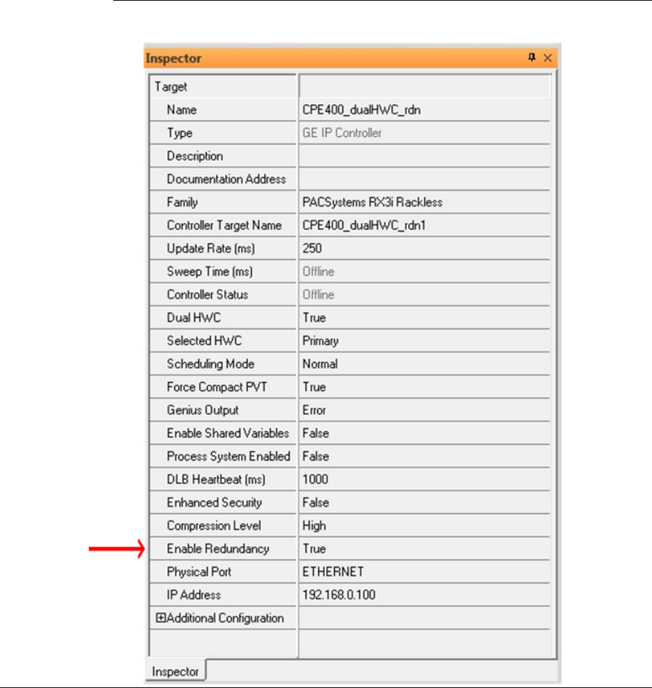
PACSystems™ RX3i Hot Standby CPU Redundancy User Manual Section 5
GFK-2308W May 2021
Configuration Requirements 47
Figure 16: Enable Redundancy in CPE400
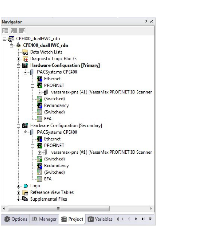
PACSystems™ RX3i Hot Standby CPU Redundancy User Manual Section 5
GFK-2308W May 2021
Configuration Requirements 48
1) Once the Enable Redundancy target property is set to True, PME generates a secondary
HWC and includes it in the target (Figure 17).
i. Refer to the PME Help page for information concerning other CPE400/CPL410
properties that are also changed as a result of enabling redundancy.
ii. If the Enable Redundancy property is changed back to False, the Secondary HWC is
automatically removed.
Figure 17: Generate Secondary CPE400 Hardware Configuration
2) Redundancy and Transfer List tabs are also added to the configuration parameters
window for the CPE400/CPL410 (Figure 17). Refer to Section 6.5 for a discussion of Fail
Wait Time. Refer to Section 6.6 for a discussion of Data Transfer, including Transfer Lists.
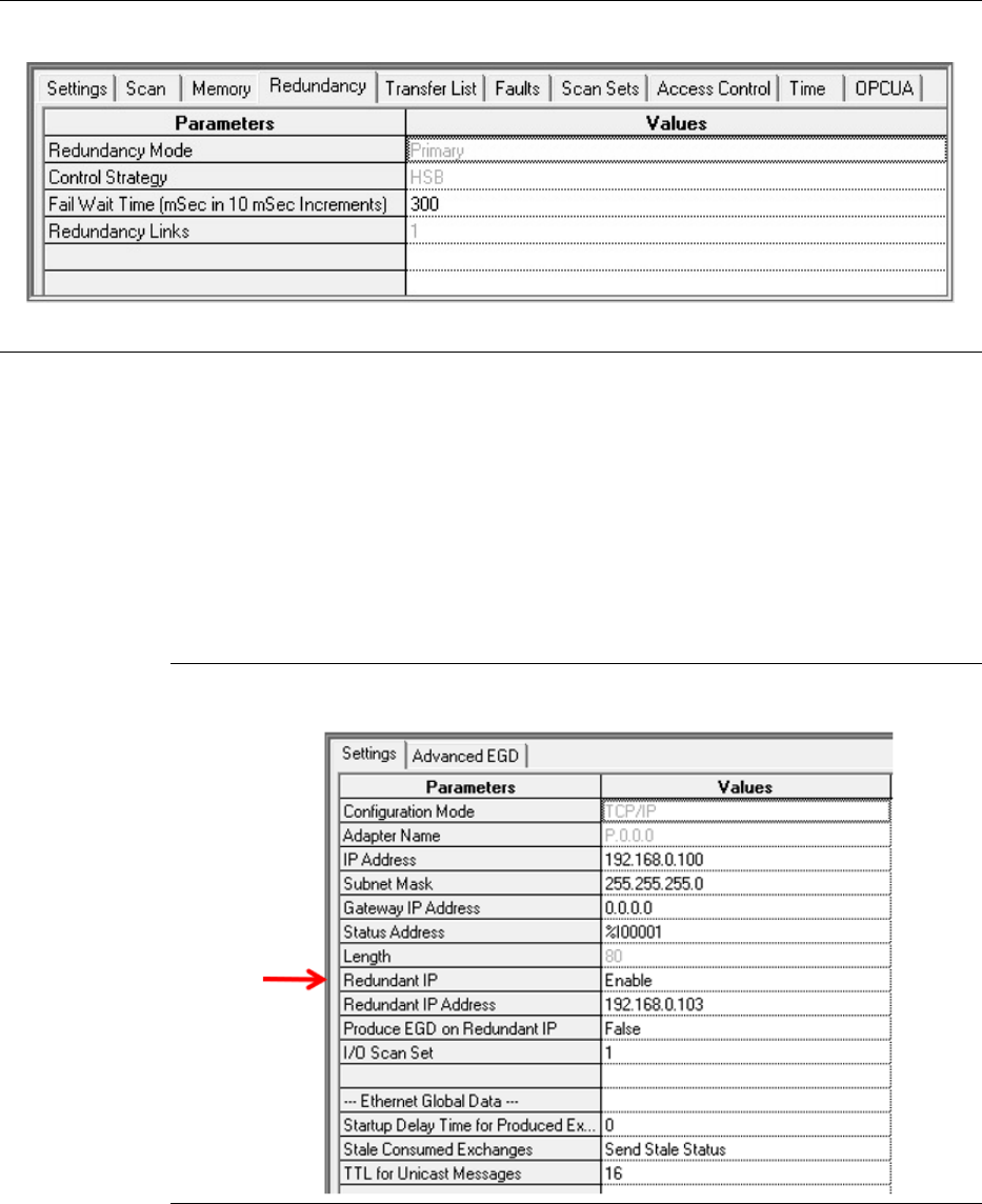
PACSystems™ RX3i Hot Standby CPU Redundancy User Manual Section 5
GFK-2308W May 2021
Configuration Requirements 49
Figure 18: Redundancy tab & Transfer List tab Associated with CPE400
3) The CPE400/CPL410 supports a Redundant IP address on LAN1 (Ethernet or PROFINET)
and on LAN2 (Ethernet only). Refer to Section 5.4.4, Ethernet Interface Parameters.
i. Redundant IP is disabled by default, so be sure to manually enable it (Figure 19)
whenever it is required for the application.
ii. Redundant IP is supported by the SRTP Server, Modbus TCP Server, and EGD protocols.
iii. The CPE400/CPL410 OPC UA Server and Ethernet firmware update web page are
available in a redundant system using the direct IP addresses of the primary and
secondary CPUs; they are not available via the Redundant IP address.
Figure 19: Enable CPE400 Redundant IP (LAN1)
4) RX3i PROFINET redundant applications may be migrated between CRU320, CPE330,
CPE400 and CPL410.
PACSystems™ RX3i Hot Standby CPU Redundancy User Manual Section 5
GFK-2308W May 2021
Configuration Requirements 50
Restrictions for CPE400/CPL410 Redundancy
1) In the CPE400 and CPL410, the PNC functionality is only supported by Ethernet ports (on
LAN2 only), configured as an embedded PROFINET Controller.
2) Only one PROFINET I/O network may be configured in a CPE400/CPL410 system. The
number of PROFINET devices is limited to:
i. CPE400 – 32 (simplex) or 20 (Hot Standby Redundancy).
ii. CPL410 – 64 (simplex) or 32 (Hot Standby Redundancy).
3) LAN3 is reserved for Redundancy Communications. No additional Ethernet hardware may
be attached to this network. Only the Primary and Secondary CPUs may be
interconnected on LAN3.
4) To support Hot Standby Redundancy with Genius I/O, the CPE400 or CPL410 CPU must
employ its embedded PROFINET Controller and interface with Genius devices via the RX3i
Genius Communications Gateway (GCG) IC695GCG001. The CPE330 may also be
configured to use its embedded PROFINET Controller in such a configuration. Similar
configurations have been tested using other RX3i CPUs combined with rack-mounted
PROFINET Controllers (IC695PNC001). GE Automation & Controls does not see any
reason why configurations employing an embedded PROFINET Controller would not work
equally well. However, testing with embedded PROFINET Controllers has not been
conducted at this time.
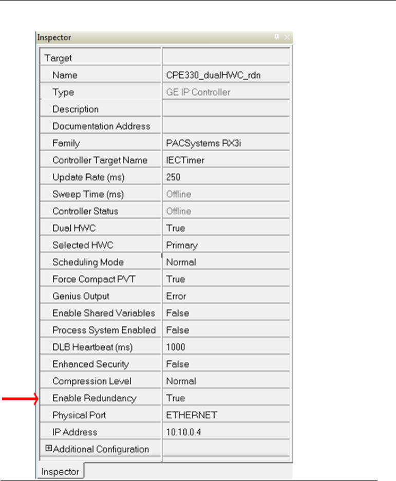
PACSystems™ RX3i Hot Standby CPU Redundancy User Manual Section 5
GFK-2308W May 2021
Configuration Requirements 51
5.1.2 Setting up a CPE330 for Redundancy
Step by Step instructions for Configuring Redundancy on
CPE330
1) Use PAC Machine Edition 8.60 SIM 8 or later to create native CPE330 redundant
applications.
2) To enable redundancy in a CPE330 project, select the CPE330 target in the PME Navigator
and use the Property Inspector to change the Enable Redundancy target property to True
(Figure 20).
Figure 20: Enable Redundancy in CPE330 Target
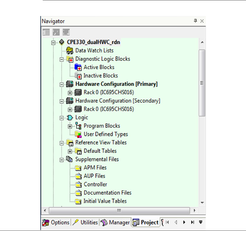
PACSystems™ RX3i Hot Standby CPU Redundancy User Manual Section 5
GFK-2308W May 2021
Configuration Requirements 52
3) Once the Enable Redundancy target property is set to True, PME generates a secondary
HWC and includes it in the target (Figure 21).
a. Refer to the PME Help page for information concerning other CPE330 properties
that are also changed as a result of enabling redundancy.
b. If the Enable Redundancy property is changed back to False, the Secondary HWC is
automatically removed.
Figure 21: Generate CPE330 Secondary Hardware Configuration
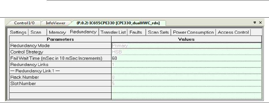
PACSystems™ RX3i Hot Standby CPU Redundancy User Manual Section 5
GFK-2308W May 2021
Configuration Requirements 53
4) Redundancy and Transfer List tabs are also added to the configuration parameters
window for the CPE330 (Figure 22). (Refer to 6.5 for a discussion of Fail Wait Time.
5) Refer to Section 6.6 for a discussion of Data Transfer, including Transfer Lists.
Figure 22: Redundancy tab & Transfer List tab Associated with CPE330
6) The CPE330, CPE400, and CPL410 all support two Redundant IP addresses, one for each
of the embedded Ethernet LANs: LAN1 and LAN2 (Figure 23). For additional details, refer
to Section 5.4.4, Ethernet Interface Parameters.
a. Redundant IP is disabled by default, so be sure to manually enable it whenever it is
required for the application.
b. Redundant IP is supported by the SRTP Server, Modbus TCP Server, and EGD
protocols.
c. The CPE330 OPC UA Server and Ethernet firmware update web page are available in a
redundant system using the direct IP addresses of the primary and secondary CPUs;
they are not available via the Redundant IP address.
7)RX3i PROFINET redundant applications may be migrated between CRU320, CPE330,
CPE400, and CPL410.
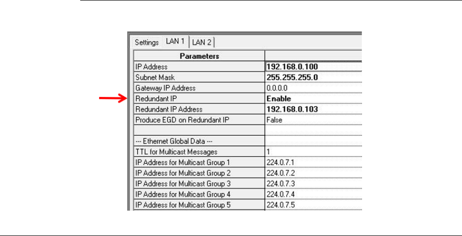
PACSystems™ RX3i Hot Standby CPU Redundancy User Manual Section 5
GFK-2308W May 2021
Configuration Requirements 54
Figure 23: Enable CPE330 Redundant IP (LAN1/LAN2)
Restrictions for CPE330 Redundancy
1) In the CPE330, the PNC functionality is supported by Ethernet ports on LAN2,
configured as an embedded PNC.
2) The number of PROFINET devices is limited to 32, 20 of which may be redundant.
3) RMX modules are required. High-speed LANs cannot be used as a substitute
redundancy link.
PACSystems™ RX3i Hot Standby CPU Redundancy User Manual Section 5
GFK-2308W May 2021
Configuration Requirements 55
5.2 PROFINET I/O Configuration
This section details how to configure an HSB CPU Redundancy system that uses
redundantly controlled PROFINET I/O.
5.2.1 Requirements
When using redundantly controlled PROFINET I/O in an HSB CPU Redundancy
system, the following requirements apply:
o The HSB CPU Redundancy system must be configured as a Dual HWC target.
When you select a Redundant CPU, the programming software
automatically presents the Dual HWC Target. The programming software
will not permit redundantly controlled PROFINET I/O Devices to be
configured in a standalone (non-redundant) target.
o Physically set up the CPU Redundancy Link. There are two methods,
depending on CPU type:
o For RX3i rack-based systems, the HSB CPU Redundancy target can be
configured with a minimum of one redundancy link (one RMX module in
each unit). Any failed redundancy link should be repaired as soon as possible.
o For CPE400 and CPL410, both ports on LAN3 are used for Redundancy. This
provides the high-speed Ethernet Communications link used in place of the
traditional RMX modules. No other equipment may be introduced onto
LAN3. Each port on the Primary CPU is directly connected to the equivalent
port in the Backup (upper to upper and lower to lower). The system will
operate with only one Ethernet link operating on LAN3, but both links should
be connected to provide for redundancy on the communications link itself.
o To be redundantly controlled, a PROFINET device must support PROFINET
System Redundancy. In addition, be sure to use a GSDML file for the device
(version 2.3 or later) which indicates that the device supports PROFINET
System Redundancy.
o To ensure that they are configured consistently at both units, any additions,
modifications, or deletions of redundantly controlled PROFINET I/O Devices
must be configured in the Primary hardware configuration (HWC) and then
mirrored to the Secondary HWC.
o All inputs assigned to redundantly controlled PROFINET I/O Devices must be
included in the CPU’s input transfer list. (This includes all inputs assigned to
the PROFINET Scanner module.) All outputs assigned to redundantly
controlled PROFINET IO Devices must be included in the CPU’s output
transfer list.
o All inputs and outputs assigned to redundantly-controlled PROFINET I/O
Devices must be assigned to an I/O scan set that is scanned at every sweep
(such as the default Scan Set 1).
5.2.2 Restrictions
When using redundantly controlled PROFINET I/O in an HSB CPU Redundancy
system, the following restrictions apply:
PACSystems™ RX3i Hot Standby CPU Redundancy User Manual Section 5
GFK-2308W May 2021
Configuration Requirements 56
➢ Do not use any other type of redundantly controlled I/O such as Genius
devices or Ethernet NIUs.
➢ Do not use the DO_IO function block with redundantly controlled PROFINET
inputs or outputs.
➢ Do not use the SCAN_SET_IO function block with redundantly controlled
PROFINET inputs or outputs.
➢ Do not use the SUS_IO function block.
➢ Do not use the Skip Next I/O Scan (SVC_REQ 45) service request function
block.
➢ Do not use the Disable Data Transfer Copy in Backup Unit (SVC_REQ 43)
service request function block.
➢ Do not use I/O point fault contacts with redundantly controlled PROFINET
outputs.
5.2.3 Generating the Hardware Configuration
To generate the hardware configuration for redundantly controlled PROFINET I/O
1. Add and configure the PROFINET I/O Controllers (PNCs) in the Primary HWC
2. Configure the LANs
3. Add the PROFINET I/O Devices to the Primary HWC
4. Mirror the Primary HWC to the Secondary HWC
5. Set any parameters unique to the Secondary HWC
Location of the PROFINET I/O Controller
In rack-mounted systems, first select an empty slot in the Primary HWC of the
Navigator window, right-click it, select Add Module, and select the PROFINET I/O
Controller. Then attach the PNC to a new or existing LAN.
In CPL410 systems, configure LAN2 as an embedded PROFINET Controller (refer to
the PACSystems RX3i IC695CPL410 1.2GHz 64MB Rackless CPU w/Linux Quick Start
Guide, GFK-3053).
In CPE400 systems, configure LAN2 as an embedded PROFINET Controller (refer to
the PACSystems RX3i IC695CPE400 1.2GHz 64MB Rackless CPU w/Field Agent Quick Start
Guide, GFK-3002).
In CPE330 systems, LAN2 may be configured as an embedded PROFINET Controller
for redundantly controlled PROFINET I/O. (Refer to PACSYSTEMS RX3i 1GHz 64MB CPU
w/Ethernet Quick Start Guide, GFK-2941.)
For more information regarding the configuration of the PROFINET IO Controller,
refer to the RX3i PROFINET Controller Manual, GFK-2571, Chapter 3: Configuration –
Configuring an RX3i PROFINET Controller.
Note: When redundantly-controlled I/O Devices are configured at a PNC module, the
programming software always sets the Mirror to Secondary property for that PNC to
True.
PACSystems™ RX3i Hot Standby CPU Redundancy User Manual Section 5
GFK-2308W May 2021
Configuration Requirements 57
Configuring the PROFINET LANs
For information regarding how to configure a PROFINET LAN, refer to the RX3i
PROFINET Controller Manual, GFK-2571, Chapter 3, Configuration – Configuring
PROFINET LANs.
Transfer List Auto-Expansion
All inputs assigned to redundantly controlled PROFINET I/O Devices must be included
in the CPU’s input transfer list and all outputs assigned to redundantly controlled
PROFINET I/O Devices must be included in the CPU’s output transfer list.
For convenience, the programming software automatically expands the length of the
input or output transfer list to include the reference addresses of any newly added or
modified redundantly controlled PROFINET I/O devices or modules. Whenever you
add a redundantly controlled PROFINET I/O Device or module, you should check the
CPU’s transfer list to ensure the adjusted starting addresses and lengths do not
include reference memory that was not intended to be transferred. If the reference
addresses assigned to redundantly controlled PROFINET I/O are already included in
the current transfer list, the transfer list will not be modified by the programming
software.
To avoid unintended inclusion of reference addresses in the transfer list, it is
recommended that you allocate the memory ranges planned for redundantly
controlled PROFINET I/O as a contiguous block near the end of the %I, %Q, %AI, or
%AQ tables, allowing room for the future addition of redundantly controlled
PROFINET I/O devices or modules. If the addition of future devices or modules using
%I, %Q, %AI, or %AQ reference addresses is likely and must be done without stopping
the process (refer to Section 5.2.5, Adding or Modifying a PROFINET I/O Device without
Stopping the Process), adding some or all of the remaining memory to the transfer list
can simplify the process, but is not necessary. For information regarding the CPU
scan time impact per byte of memory added to the transfer list, refer to Section
6.6.2, Estimating Data Transfer Time.
Configuring Redundantly Controlled PROFINET Devices
To add a redundantly controlled PROFINET I/O device to the HWC, first select the PNC
in the Primary HWC of the Navigator window, right-click on it, and select Add I/O
Device.
In the PROFINET Device Catalog, select the entry that corresponds to the device. You
must use a GSDML file for the device that is at least version 2.3 and indicates that the
device supports PROFINET System Redundancy.
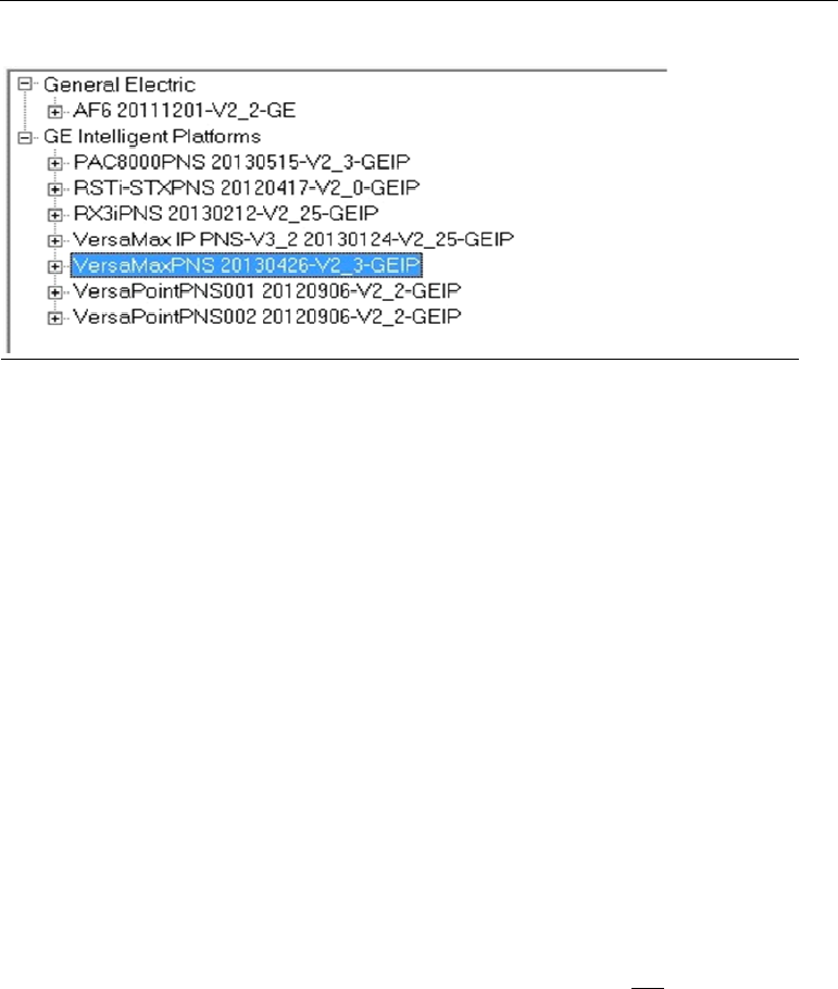
PACSystems™ RX3i Hot Standby CPU Redundancy User Manual Section 5
GFK-2308W May 2021
Configuration Requirements 58
Figure 24: PROFINET Device Selection
For each device added, the programming software provides a Redundancy tab and
sets the Redundancy Mode parameter on that tab to HSB CPU Redundancy.
For additional information regarding the configuration of the VersaMax PROFINET
Scanner, refer to the RX3i PROFINET Controller Manual, GFK-2571, Chapter 3,
Configuration - Adding a VersaMax PROFINET Scanner to a LAN.
Configuring Simplex PROFINET Devices
A Hot Standby CPU Redundancy system can contain both redundantly controlled and
simplex (non-redundantly controlled) PROFINET I/O Devices. A simplex I/O Device is
always controlled by one of the two units (either Primary or Secondary) and will
always be controlled by that unit regardless of whether that unit is Active or Backup.
To configure a device that supports PROFINET System Redundancy as a simplex
device for the Primary CPU, add that device to the Primary HWC and set the
Redundancy Mode parameter on its Redundancy tab to None.
To configure a device that supports PROFINET System Redundancy as a simplex
device for the Secondary CPU, add that device to the Secondary CPU’s HWC. The
programmer automatically sets the Redundancy Mode parameter on its Redundancy
tab to None.
During mirror operations, simplex devices in the Primary’s HWC are not copied to the
Secondary’s HWC, and simplex devices in the Secondary’s HWC are not affected.
PACSystems™ RX3i Hot Standby CPU Redundancy User Manual Section 5
GFK-2308W May 2021
Configuration Requirements 59
Configuring PROFINET Media Redundancy
PROFINET media redundancy is described in the RX3i PROFINET Controller Manual,
GFK-2571, Chapter 6, Redundant Media. All nodes participating in the media
redundancy ring must be configured for media redundancy operation.
When using PROFINET media redundancy in an HSB CPU Redundancy system,
configure the PROFINET Controller (PNC) module in the Primary CPU system as the
media redundancy manager. All of the other nodes that participate in the ring (for
example, the corresponding PNC module in the Secondary CPU, other PNC modules,
I/O devices, other PNC modules, switches) must be configured as media redundancy
clients. If the system uses multiple independent LANs, configure exactly one PNC
module on each LAN as the media redundancy manager.
When a PNC is added to the HWC, it is not set up for media redundancy. A PNC
module can be configured as either a media redundancy manager or client on the
Media Redundancy tab according to the RX3i PROFINET Controller Manual, GFK-2571,
Chapter 3, Configuration.
Note: To avoid network problems, be sure to follow the instructions in the RX3i
PROFINET Controller Manual, GFK-2571, Chapter 6, Redundant Media, when initially
setting up a media redundancy network, when enabling or disabling media
redundancy in an I/O network, or when replacing a PNC module configured as the
media redundancy manager.
Configuring Critical Network Ports
Critical Network Ports are described in the RX3i PROFINET Controller Manual, GFK-
2571, Chapter 3, Configuration - PROFINET Controller Parameters (Settings Tab).
To force a role switch when one or more of the PROFINET Controller module’s
network ports is disconnected from the network, configure the desired network
port(s) as critical. When all of the critical network ports are disconnected from their
networks, the PROFINET Controller logs a diagnostic fault. If the PROFINET Controller
is controlling redundant devices, the diagnostic fault results in a CPU redundancy role
switch with the CPU placed into Stop/Fault mode.
Note: Detecting that 1000 Mbps copper fixed or copper SFP ports are disconnected
(link loss) does not occur fast enough to invoke a role switch without losing devices.
This is the result of the IEEE specification that states that copper ports running at
1000 Mbps must have a 750 ms link down detection time. Therefore, networks
running at 100 Mbps are recommended as they have a very fast link down detection
time. Also, copper fixed or copper SFP ports configured as Critical Network ports
connected to 1000 Mbps networks are forced to auto-negotiate to 100 Mbps.
Synchronizing PROFINET I/O Configuration to Secondary
Hardware Configuration
When you have finished adding, modifying, or deleting redundantly-controlled
PROFINET I/O devices in the Primary configuration, you must synchronize those
changes to the Secondary configuration. To do this, right-click the Hardware
Configuration [Primary], choose Redundancy, and then choose Mirror to Secondary
Hardware Configuration. This command copies the Primary’s configuration (those
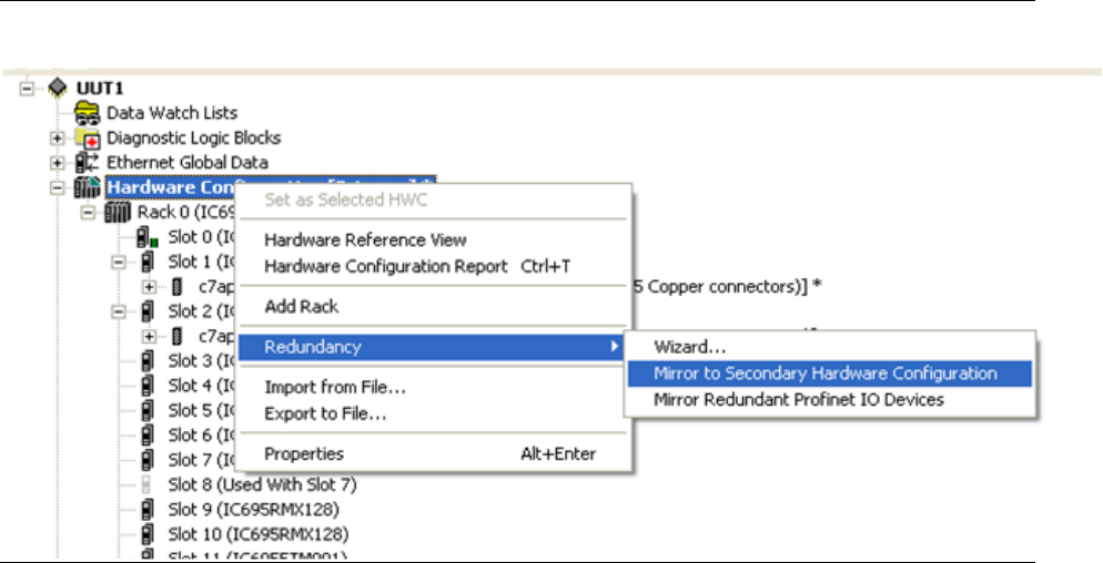
PACSystems™ RX3i Hot Standby CPU Redundancy User Manual Section 5
GFK-2308W May 2021
Configuration Requirements 60
modules that have their Mirror to Secondary property set to True) to the Secondary’s
configuration. The redundantly controlled PROFINET I/O devices are included in this
copy.
Figure 25: Mirror Hardware Configuration to Secondary CPU
You will receive a prompt that this mirroring operation cannot be undone; select Yes
to continue.
If this mirror operation has added a new PNC to the Secondary’s HWC, be sure to set
the following parameters for that PNC:
• The PROFINET Controller’s Device Name
• The PROFINET Controller’s IP Address
If this mirror operation has added a new Ethernet module to the Secondary’s HWC,
be sure to set the IP Address of that Ethernet Interface (refer to Section 5.4.4,
Ethernet Interface Parameters).
After mirroring, check the following in the Primary and Secondary configurations:
• PNC device name and IP address are correct in the Secondary configuration.
These parameters must be different from the Primary configuration.
• All redundantly-controlled PROFINET inputs are included in the Primary and
Secondary CPUs’ Input transfer lists.
• All redundantly controlled PROFINET outputs are included in the Primary and
Secondary CPUs’ Output transfer lists.
The Secondary CPU’s transfer lists match the Primary CPU’s transfer lists.
• The Ethernet module IP addresses are correct in the Secondary
configuration.
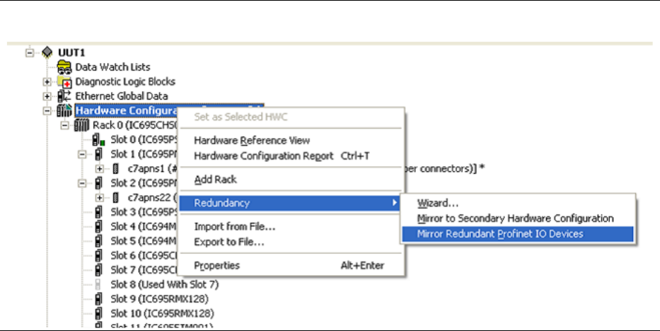
PACSystems™ RX3i Hot Standby CPU Redundancy User Manual Section 5
GFK-2308W May 2021
Configuration Requirements 61
Mirroring Redundantly Controlled PROFINET Devices to
Secondary
When the only changes to an existing Primary hardware configuration are addition,
modification, or deletion of redundantly-controlled PROFINET IO devices, you can
choose to mirror only those devices to the Secondary configuration. To do this right-
click the Hardware Configuration [Primary], choose Redundancy, and then choose
Mirror Redundant PROFINET I/O Devices. This command copies only the redundantly-
controlled PROFINET I/O devices from the Primary HWC to the Secondary HWC.
Figure 26: Mirror PROFINET I/O Devices to Secondary CPU

PACSystems™ RX3i Hot Standby CPU Redundancy User Manual Section 5
GFK-2308W May 2021
Configuration Requirements 62
5.2.4 Downloading PROFINET I/O Configuration to the HSB
CPU Redundancy System
This section describes recommended sequences for downloading configurations
containing PROFINET I/O from the PAC Machine Edition programming software into
an HSB CPU redundancy system. Before downloading, generate the Primary and
Secondary configurations as described in Section 5.2.3, Generating the Hardware
Configuration.
The recommended download sequence varies according to the situation:
• Initial Download to Redundancy System
• Download a Modified Configuration to a Redundancy System – Stopping the Process
• Add/Modify a PROFINET Device Using Reference Memory without Stopping the
Process
• Add/Modify a PROFINET Device Using I/O Variables without Stopping the Process
Initial Download to Redundancy System
This is the sequence for downloading configurations into a new redundancy system.
Both units are initially stopped with no configuration. For this procedure refer to
Section 2:, RX3i Hot Standby Redundancy Quick Start with PROFINET I/O.
Download a Modified Configuration to a Redundancy
System – Stopping the Process
This is the sequence for downloading modified configurations to a redundant target
that is already configured and running. Either unit can be the Active unit. This
download sequence stops both units.
1) Stop and Clear the Secondary CPU.
a. Select the Secondary CPU. Stop the Secondary CPU. If the Secondary CPU was the
Active unit, the Primary CPU becomes the Active unit.
b. Clear the Secondary CPU’s HWC. (If logic and HWC are coupled, select Program
option in the Clear Memory dialog; this will clear both logic and HWC.
c. Clear the Secondary CPU’s Controller and I/O Fault Tables.
2) Stop and Download the Primary CPU
a. Select the Primary CPU. Stop the Primary CPU.
b. Expect the Primary CPU to log a Loss of Device and an Add’n of Device fault for
each redundantly controlled I/O Device. For example:
0.1.D2
Add'n of Device
0.1.D2
Loss of Device

PACSystems™ RX3i Hot Standby CPU Redundancy User Manual Section 5
GFK-2308W May 2021
Configuration Requirements 63
c. Clear the Primary CPU’s Controller and I/O Fault Tables.
d. Download the revised HWC to the Primary CPU. (If logic and HWC are coupled,
select both Hardware Configuration and Logic in the Download to Controller
dialog.)
Expect the Primary CPU to log a Redundancy link communication failure
Controller fault for each RMX module. For example:
0.9
Redundancy link communication failure
0.10
Redundancy link communication failure
e. Confirm that the Primary CPU did not record any unexpected Loss of Device
faults in its I/O Fault table.
3) Download the Secondary CPU
a. Select the Secondary CPU.
b. Download the revised HWC to the Secondary CPU. (If logic and HWC are
coupled, select Hardware Configuration and Logic in the Download to
Controller dialog.)
c. Confirm that the LINK OK LEDs are ON for both RMX modules in both units
(this could take a few seconds)
d. Confirm that the Secondary CPU did not record any unexpected Loss of Device
faults in its I/O fault table.
4) Start the Primary and Secondary CPUs
a) Select the Primary CPU and put it into Run mode.
b) Select the Secondary CPU and put it into Run mode.
5) [Optional] The logic application in the Primary and Secondary CPUs can examine the
All Devices Connected module status bit at each PNC module.

PACSystems™ RX3i Hot Standby CPU Redundancy User Manual Section 5
GFK-2308W May 2021
Configuration Requirements 64
5.2.5 Adding or Modifying a PROFINET I/O Device without
Stopping the Process
It is possible to add a new redundantly controlled PROFINET IO device, or add I/O
module(s) to an existing redundantly controlled PROFINET I/O device in an HSB CPU
redundancy system that is already running without stopping the application process.
The procedures differ, depending upon whether the PROFINET I/O device uses
reference memory or I/O variables. Both procedures are presented below.
Add/Modify a PROFINET Device Using Reference Memory
without Stopping the Process
If the new I/O Device or new I/O module(s) will use reference memory, use this
procedure. If the new reference memory locations are not already in the transfer lists,
you must first modify the transfer lists and execute a dual run-mode-store of the
revised transfer lists before you add the new I/O device and/or I/O module(s) to the
configuration.
WARNING
This procedure allows you to modify a device’s Hardware Configuration without stopping
the process that is being controlled. However, that device's inputs and outputs will
default and remain defaulted for a short period of time during this procedure.
When adding a new I/O device, determine the I/O network on which you will add this
device. If you have not already assigned the network name for this device, assign it
now. You can do this from the programming software by right-clicking the PNC
module and selecting Launch Discovery Tool. For more information, refer to the
PACSystems RX3i PROFINET Controller Manual, GFK-2571, Chapter 3, Configuration -
Assigning I/O Device Names.
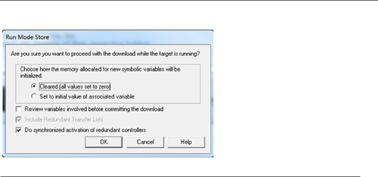
PACSystems™ RX3i Hot Standby CPU Redundancy User Manual Section 5
GFK-2308W May 2021
Configuration Requirements 65
Update Transfer Lists
1. Display the Primary CPU’s Transfer List tab. Record the starting addresses
and lengths for %I and %AI of the Input Transfer Point. Record the starting
addresses and lengths for the %Q and %AQ of the Output Transfer Point.
2. Determine the list of modules to be added to the device. (For a new device, also
include the head-end in the list.) Use this module list during steps 3 of this
section and step 2 in Section Add new Device and/or Modules to Hardware
Configuration below.
3. For each module in the list, determine the reference memory ranges to be
added for this module. Then determine the overall reference memory ranges
used by this new or modified device.
4. If the overall reference memory ranges for this device are already present in the
CPU’s transfer lists, the transfer lists do not need to be revised. Proceed to step 1
in Section Add new Device and/or Modules to Hardware Configuration to edit and
download the Hardware Configuration.
5. If the overall reference memory ranges for this device fall outside of the
CPU’s transfer lists, edit the Primary CPU’s transfer list to include the
reference memory ranges used by this device. Also, update the Transfer List
starting addresses and lengths.
6. Confirm that both the Primary and Secondary CPUs are in Run mode and that
the LINK OK LEDs are ON for both RMX modules in both units.
7. Connect the programming software to the Primary CPU.
8. Initiate a download to the controller. Be sure to leave the box next to Do
synchronized activation of redundant controllers checked. Press OK.
Figure 27: Run Mode Store Options at Download
9. Disconnect the programming software.
10. Connect the programming software to the Secondary CPU.
11. Initiate a download to the controller. Be sure to leave the box next to Do
synchronized activation of redundant controllers checked. Press OK.

PACSystems™ RX3i Hot Standby CPU Redundancy User Manual Section 5
GFK-2308W May 2021
Configuration Requirements 66
12. Disconnect the programming software.
Add new Device and/or Modules to Hardware Configuration
1. For a new device, add the new device to the Primary CPU’s Hardware
Configuration.
2. Add modules to the device in the Primary CPU’s Hardware Configuration. For
each module in a new device (including the head-end), or for each new
module in an existing device, do the following:
a. Make sure the module’s Variable Mode property to False (the default
value).
b. Set the module’s Reference Address parameters. (These were recorded in
the module list.
3. Display the Primary CPU’s Transfer List tab and readjust the CPU Transfer
Lists to the reference memory ranges that you previously recorded. Set the
starting addresses and lengths for %I and %AI of the Input Transfer Point to
the recorded values. Set the starting addresses and lengths for the %Q and
%AQ of the Output Transfer Point to the recorded values.
Note: During validation, the programming software automatically mirrors
redundantly controlled PROFINET devices from the Primary hardware configuration
to the Secondary hardware configuration. You do not need to manually mirror the
new or modified PROFINET device.
Download Hardware Configuration to both units
1. Connect the programming software to the Backup unit.
2. Stop the Backup unit.
3. Initiate a download to the controller. Select Hardware Configuration in the
Download to Controller dialog. When the download completes:
If changing the configuration of an existing device:
a. Confirm that the LINK OK LEDs are ON for both RMX modules in both units
(this may take a few seconds).
b. Wait approximately 10 seconds to give the stopped unit time to connect to
all of its unmodified PROFINET devices.
0.5.D2
Loss of Device
c. Expect this unit to log a Loss of Device fault in its I/O Fault table for the
device undergoing Hardware Configuration changes. This occurs because
this unit’s copy of the device’s Hardware Configuration does not match the
other unit’s copy.
d. Because at least one configured device is not connected, the ACTIVE LED on
the corresponding PNC should become solid amber.
e. Confirm that the stopped unit did not record any unexpected Loss of Device
faults in its I/O fault table.

PACSystems™ RX3i Hot Standby CPU Redundancy User Manual Section 5
GFK-2308W May 2021
Configuration Requirements 67
Note: If a role switch or a control takeover occurs before a device connects to this
unit, that device’s inputs and outputs will default.
If adding a new device only:
a) Confirm that the LINK OK LEDs are ON for both RMX modules in both units
(this may take a few seconds)
b) Wait approximately 10 seconds to give the stopped unit time to connect to
all of its unmodified PROFINET devices.
c) If all of the devices configured for a PNC are present, that PNC’s ACTIVE LED
should become solid green. If one or more devices are not present, confirm
that the stopped unit did not record any unexpected Loss of Device faults in
its I/O Fault table.
d) Put the stopped unit into Run mode.
Note: If a role switch or a control takeover occurs before a device connects to this
unit, that device’s inputs and outputs will default.
If adding a new device only:
Optional: If you would like to switch control to this unit before it happens
automatically in step b, you can request a role switch now.
a. Disconnect the programming software.
a. Connect the programming software to the other unit.
b. Stop that unit
If changing the configuration of an existing device:
a. The modified device’s inputs and outputs will default and remain defaulted
until step 26.
c. The stopped unit will log a Loss of Device fault for that device in its I/O
Fault table.
0.5.D2
Loss of Device
d. The stopped unit may log an Add’n of Device fault for that device in its I/O
Fault table.
0.5.D2
Add'n of Device
e. Initiate a download to the controller. Select Hardware Configuration in the
Download to Controller dialog. When the download completes:
f. Confirm that the LINK OK LEDs are ON for both RMX modules in both units
(this may take a few seconds).

PACSystems™ RX3i Hot Standby CPU Redundancy User Manual Section 5
GFK-2308W May 2021
Configuration Requirements 68
g. Wait approximately 10 seconds to give the stopped unit time to connect
to all of its PROFINET devices.
If changing the configuration of an existing device:
Within this 10 second interval, expect I/O to resume on the device that
was modified, and expect the running unit to log an Add’n of Device
fault for that device in its I/O Fault Table.
0
.
5
.
D
2
Add'
n of
Devi
ce
a. If all of the devices configured for a PNC are present, that PNC’s ACTIVE
LED should become solid green. If one or more devices are not present,
confirm that the stopped unit did not record any unexpected Loss of
Device faults in its I/O fault table. Note: If a role switch or a control
takeover occurs before a device connects to this unit, that device’s inputs
and outputs will default.
h. Put the stopped unit into Run mode. This unit now becomes the Backup
unit. If desired, request a role switch to make this unit the Active unit
i. Disconnect the programming software.
Add/Modify a PROFINET Device Using I/O Variables without
Stopping the Process
This is the sequence for adding a new PROFINET I/O device, or adding IO modules(s)
to an existing PROFINET I/O device, when the PROFINET IO device uses I/O variables.
If the new I/O Device or new I/O module(s) will use I/O Variables, use this procedure.
This procedure requires you to create the I/O variables and execute a dual run-mode-
store of the revised transfer lists before you add the new I/O device and/or I/O
module(s) to the configuration.
WARNING
This procedure allows you to modify a device’s Hardware Configuration without
stopping the process that is being controlled. However, that device’s inputs and
outputs will default and remain defaulted for a short period of time during this
procedure.
1. When adding a new I/O device, determine the I/O network on which you
will add this device. If you have not already assigned the network name for
this device, assign it now. You can do this from the programming software
by right-clicking on the PNC module and selecting Launch Discovery Tool.
For more information, refer to the PACSystems RX3i PROFINET Controller
Manual, GFK-2571, Chapter 3, Configuration - Assigning I/O Device Names.
PACSystems™ RX3i Hot Standby CPU Redundancy User Manual Section 5
GFK-2308W May 2021
Configuration Requirements 69
Create I/O Variables
2. Display the Primary CPU’s Transfer List tab. Record the starting addresses
and lengths for %I and %AI of the Input Transfer Point. Record the starting
addresses and lengths for the %Q and %AQ of the Output Transfer Point.
3. Determine the list of modules to be added to the device. (For a new device,
also include the head-end in the list.) Use this list during steps 3 through 6
below.
Note: Do not add the device or module(s) to the Hardware Configuration until step
15.
4. For each module in your list that will have discrete inputs:
a. Create a new variable of Data Type BOOL.
b. Set the Array Dimension 1 property to the number of input points
provided by the module.
c. Set the Ref Address property to an unused %I location.
d. Set the Input Transfer List property to True.
5. For each module in your list that will have discrete outputs:
a. Create a new variable of Data Type BOOL.
b. Set the Array Dimension 1 property to the number of output points
provided by the module.
c. Set the Ref Address property to an unused %Q location.
d. Set the Output Transfer List property to True.
6. For each module in your list that will have analog inputs:
a. Create a new variable of Data Type WORD.
b. Set the Array Dimension 1 property to the number of channels provided
by the module.
c. Set the Ref Address property to an unused %AI location.
d. Set the Input Transfer List property to True.
7. For each module in your list that will have analog outputs:
a. Create a new symbolic variable of Data Type WORD.
b. Set the Array Dimension 1 property to the number of channels provided
by the module.
c. Set the Ref Address property to an unused %AQ location.
d. Set the Output Transfer List property to True.
Download the Revised Transfer Lists to Both Units (Dual Run-mode Store)
8. Confirm that both the Primary and Secondary CPUs are in Run mode and
that the LINK OK LEDs are ON for both RMX modules in both units.
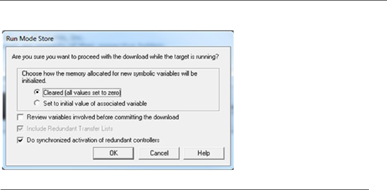
PACSystems™ RX3i Hot Standby CPU Redundancy User Manual Section 5
GFK-2308W May 2021
Configuration Requirements 70
9. Connect the programming software to the Primary CPU.
10. Initiate a download to the controller. Be sure to leave the box next to Do
synchronized activation of redundant controllers checked. Press OK
Figure 28: Run Mode Store Options at Download
11. Disconnect the programming software.
12. Connect the programming software to the Secondary CPU.
13. Initiate a download to the controller. Be sure to leave the box next to Do
synchronized activation of redundant controllers checked. Press OK.
14. Disconnect the programming software.
Add new Device and/or Modules to Hardware Configuration
15. For a new device, add the new device to the Primary CPU’s Hardware
Configuration.
16. Add modules to the device in the Primary CPU’s Hardware Configuration. For
each module in a new device (including the head-end), or for each new module
in an existing device, do the following:
a. Set the module’s Variable Mode property to True
b. Select module’s Terminals tab.
c. For each group of inputs and outputs shown on this tab, right-click on the
first point and select Map Variable. Select the variable that you created for
this group during steps 3 through 6.
17. Visit the Primary CPU’s Transfer List tab and readjust the CPU Transfer Lists to
original reference memory ranges as recorded in step 2. Set the starting
addresses and lengths for %I and %AI of the Input Transfer Point to the
recorded values. Set the starting addresses and lengths for the %Q and %AQ of
the Output Transfer Point to the recorded values.
Note: During validation, the programming software automatically mirrors
redundantly controlled PROFINET devices from the Primary hardware configuration

PACSystems™ RX3i Hot Standby CPU Redundancy User Manual Section 5
GFK-2308W May 2021
Configuration Requirements 71
to the Secondary hardware configuration. The user does not need to manually mirror
the new or modified PROFINET device.
18. Download Hardware Configuration to Both Units
19. Connect the programming software to the Backup unit.
20. Stop the Backup unit.
21. Initiate a download to the controller. Be sure to select both Hardware
Configuration and Logic in the Download to Controller dialog. When the
download completes:
If changing the configuration of an existing device:
a. Confirm that the LINK OK LEDs are ON for both RMX modules in both units
(this may take a few seconds).
b. Wait approximately 10 seconds to give the stopped unit time to connect
to all of its unmodified PROFINET devices.
c. Expect this unit to log a Loss of Device fault in its I/O fault table for the
device undergoing Hardware Configuration changes. This occurs because
this unit’s copy of the device’s Hardware Configuration does not match the
other unit’s copy.
0.5.D2
Loss of Device
d.
Because at least one configured device is not connected, the ACTIVE LED
on the corresponding PNC should become solid amber.
e. Confirm that the stopped unit did not record any unexpected Loss of
Device faults in its I/O fault table.
Note: If a role switch or a control takeover occurs before a device connects to this
unit, that device’s inputs and outputs will default.
If adding a new device only:
22. Confirm that the LINK OK LEDs are ON for both RMX modules in both units
(this may take a few seconds).
23. Wait approximately 10 seconds to give the stopped unit time to connect to all
of its unmodified PROFINET devices.
24. If all of the devices configured for a PNC are present, that PNC’s ACTIVE LED
should become solid green. If one or more devices are not present, confirm
that the stopped unit did not record any unexpected Loss of Device faults in its
I/O fault table.
Note: If a role switch or a control takeover occurs before a device connects to this
unit, that device’s inputs and outputs will default.
25. Put the stopped unit into Run mode.
If adding a new device only:

PACSystems™ RX3i Hot Standby CPU Redundancy User Manual Section 5
GFK-2308W May 2021
Configuration Requirements 72
Optional: If you would like to switch control to this unit before it happens
automatically in step 14, you can request a role switch now.
12. Disconnect the programming software.
13. Connect the programming software to the other unit.
14. Stop that unit.
If changing the configuration of an existing device:
a. The modified device’s inputs and outputs will default and remain defaulted
until step 26.
b. The stopped unit will log a Loss of Device fault for that device in its I/O fault
table.
0.5.D2
Loss of Device
The stopped unit may log an Add’n of Device fault for that device in its I/O fault table.
0.5.D2
Add'n of Device
26. Initiate a download to the controller. Be sure to select both Hardware
Configuration and Logic in the Download to Controller dialog. When the
download completes:
a. Confirm that the LINK OK LEDs are ON for both RMX modules in both units
(this may take a few seconds).
b. Wait approximately 10 seconds to give the stopped unit time to connect
to all of its PROFINET devices.
If changing the configuration of an existing device:
Within this 10 second interval, expect I/O to resume on the device that was
modified, and expect the running unit to log an Add’n of Device fault for
that device in its I/O fault table.
0.5.D2
Add'n of Device
c. If all of the devices configured for a PNC are present, that PNC’s ACTIVE
LED should become solid green. If one or more devices are not present,
confirm that the stopped unit did not record any unexpected Loss of
Device faults in its I/O fault table.
Note: If a role switch or a control takeover occurs before a device connects to this
unit, that device’s inputs and outputs will default.
27. Put the stopped unit into run mode. This unit now becomes the Backup unit. If
desired, request a role switch to make this unit the Active unit.
28. Disconnect the programming software.
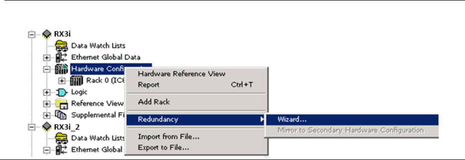
PACSystems™ RX3i Hot Standby CPU Redundancy User Manual Section 5
GFK-2308W May 2021
Configuration Requirements 73
5.3 Using the Redundancy Wizards
Machine Edition software provides redundancy wizards to create a hardware
configuration with the correct parameter settings for the redundancy scheme that
you choose. Refer to Section 5.4 Hardware Configuration Parameters.
for details on parameters specific to redundancy systems. To launch the wizard, go to
the Navigation window, right-click Hardware Configuration, point to Redundancy,
and then choose Wizard.
Figure 29: PME Redundancy Wizard
To configure a Hot Standby CPU Redundancy system using the wizards:
1. Run the Set up Primary Hardware Configuration for CPU Redundancy wizard.
This wizard configures a redundant CPU in slot 1 of the main rack and allows
you to select the location of the RMX modules used for redundancy links.
2. Complete configuration of all parameters for the Primary CPU.
3. When you have finished configuring the Primary CPU, run the Generate
Secondary Hardware Configuration from the Current Configuration wizard.
This wizard copies the Primary hardware configuration to the Secondary
configuration and adjusts appropriate parameters for the Secondary
configuration.
4. Edit the configuration parameters for each item in the Secondary CPU’s
hardware configuration that is unique for the Secondary CPU (for example, the
Secondary CPU’s direct IP address and the CPU’s SNP ID).
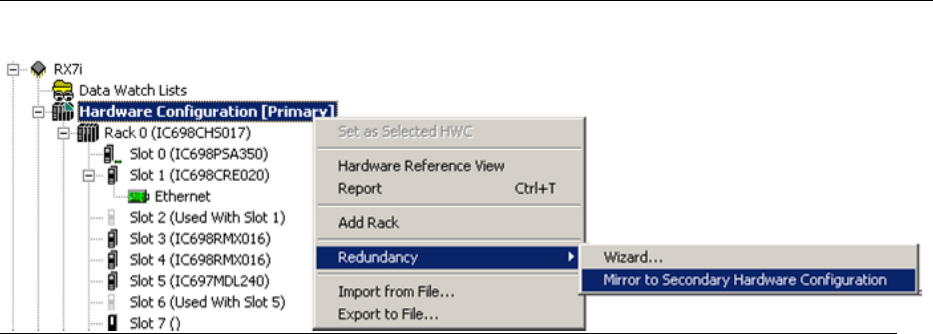
PACSystems™ RX3i Hot Standby CPU Redundancy User Manual Section 5
GFK-2308W May 2021
Configuration Requirements 74
5.3.1 Synchronizing the Hardware Configurations
To synchronize the two configurations (after making changes to the Primary
configuration or uploading a different Primary configuration), right-click Hardware
Configuration, choose Redundancy, and Mirror to Secondary Hardware
Configuration. This command copies the Primary hardware configuration to the
Secondary configuration and adjusts appropriate parameters for the Secondary
configuration.
Note: You can control whether the contents of specific slots in the Primary
configuration are copied to the Secondary configuration. If the Mirror to Secondary
property for a slot is set to True (default), the configured module in that slot in the
Primary configuration overwrites the corresponding slot in the Secondary
configuration. I/O variables associated with a module in the Primary configuration are
copied to the corresponding module in the Secondary configuration.
To prevent a slot from being mirrored, set this property to False.
Figure 30: PME Command to Mirror Configuration to Secondary Controller

PACSystems™ RX3i Hot Standby CPU Redundancy User Manual Section 5
GFK-2308W May 2021
Configuration Requirements 75
5.4 Hardware Configuration Parameters
5.4.1 CPU Parameters
This section discusses only the parameters that apply to redundancy systems. For
information on all the CPU parameters, refer to the PACSystems RX3i and RSTi-EP CPU
Reference Manual, GFK-2222.
Settings
Table 7: Hardware Configuration Parameter Definitions
Parameter
Default
Choices
Description
Stop-Mode
I/O
Scanning
Disabled
N/A
Always Disabled for a Redundant CPU.
Watchdog
Timer (ms)
200
10 through 1000, in
increments of 10 ms
Requires a value
that is greater than
the program sweep
time.
The watchdog timer, which is designed to
detect failure to complete sweep
conditions, is useful in detecting abnormal
operation of the application program,
which could prevent the CPU sweep from
completing within a specified time period.
The CPU restarts the watchdog timer at the
beginning of each sweep. The watchdog
timer accumulates time during the sweep.
In a CPU redundancy system, the watchdog
timer should be set to allow for the
maximum expected scan time plus two fail
wait times. (The Fail Wait parameter is set
on the Redundancy tab.) Furthermore, the
watchdog timer setting must allow enough
time for the CPU to complete one input
data transfer and two output data transfers.
5.4.2 Scan Parameters
Communications Window Considerations
The redundant CPU supports the use of high-speed communications modules such as
the Ethernet Interface. Requests from devices attached to these communications
modules are handled in the Controller and Backplane Communications windows.
Because these requests can be sent in large volumes, there is the potential for either
of these windows to be processing requests for a significant amount of time.

PACSystems™ RX3i Hot Standby CPU Redundancy User Manual Section 5
GFK-2308W May 2021
Configuration Requirements 76
One way to reduce the risk of one CPU failing to rendezvous at a synchronization
point with the other CPU is to configure the Controller and Backplane
Communications windows for Limited Window mode. This sets a maximum time for
these windows to run.
Other options are to configure the CPU sweep mode as Constant Window or
Constant Sweep. The CPU will then cycle through the communications and
background windows for approximately the same amount of time in both units.
Parameter
Default
Choices
Description
Sweep Mode
Normal
Normal
Constant Window
Constant Sweep.
For details on sweep modes, refer to the
PACSystems RX3i and RSTi-EP CPU Reference
Manual, GFK-2222.
Controller
Communications
Window Mode
Limited
Limited: Time sliced. The
maximum execution time for
the Controller
Communications Window per
scan is specified in the
Controller Communications
Window Timer parameter.
Complete: The window runs to
completion. There is no time
limit.
(Available only when Sweep Mode is set to
Normal.) Execution settings for the
Controller Communications Window.
Controller
Communications
Window Timer
Controller
Communications
Window Mode is:
Limited: 10
Complete: There is
no time limit.
Controller Communications
Window Mode is:
Limited: 0 through 255 ms.
Complete: Read only. There is
no time limit.
The maximum execution time for the
Controller Communications Window per
scan.
Backplane
Communications
Window Mode
Limited
Limited: Time sliced. The
maximum execution time for
the Backplane
Communications Window per
scan is specified in the
Backplane Communications
Window Timer parameter.
Complete: The window runs to
completion. There is no time
limit.
(Available only when Sweep Mode is set to
Normal.) Execution settings for the
Backplane Communications Window.
Backplane
Communications
Window Timer (ms)
10 ms for Limited
mode
Limited: Valid range: 0 through
255 ms.
Complete: Read only. There is
no time limit.
(Available only when Sweep Mode is set to
Normal.) The maximum execution time
for the Backplane Communications
Window per scan. This value can be
greater than the value for the watchdog
timer.
It is highly recommended that this
parameter be set to the same value for
both CPUs in a redundancy pair.
Background
Window Timer
5 ms
0 through 255 ms
Setting the background window time to
zero disables the background RAM tests.

PACSystems™ RX3i Hot Standby CPU Redundancy User Manual Section 5
GFK-2308W May 2021
Configuration Requirements 77
Parameter
Default
Choices
Description
Sweep Timer
(ms)
100 ms
5 through 2550 ms, in
increments of 5. If the value
typed is not a multiple of 5ms,
it is rounded to the next
highest valid value.
(Available only when Sweep Mode is set to
Constant Sweep.) The maximum overall
controller scan time. This value cannot be
greater than the value for the watchdog
timer.
Some or all of the windows at the end of
the sweep might not be executed. The
windows terminate when the overall
sweep time has reached the value
specified for the Sweep Timer parameter.
Window Timer
(ms)
10
3 through 255, in increments
of 1.
(Available only when Sweep Mode is set to
Constant Window.) The maximum
combined execution time per scan for the
Controller Communications Window,
Backplane Communications Window, and
Background Communications Window.
This value cannot be greater than the
value for the watchdog timer.
Number of Last
Scans
0
0–5 (Should be set to 0.)
The number of scans to execute after the
PACSystems CPU receives an indication
that a transition from Run to Stop mode
should occur.
In a redundancy system, this parameter
should be set to 0 (default). Using a non-
zero value would allow a unit to stay in
RUN mode for a few sweeps after
detecting a fatal fault.
Memory Parameters
Point Fault References
For applications that use redundantly controlled PROFINET I/O, the use of input point
faults is strongly recommended. By default, point faults are disabled; they must be
enabled in the CPU configuration. Select the CPU module; in the Memory tab set the
Point Fault References parameters to Enabled. For further details, refer to the
PACSystems RX3i and RSTi-EP CPU Reference Manual, GFK-2222.
Fault Parameters
Table 8: Fault Parameter Definition
Parameter
Default
Choices
Description
Recoverable
Local Memory
Error
Diagnostic
Diagnostic
Fatal
Redundant CPUs only.
Determines whether a single-bit ECC error causes
the CPU to stop or allows it to continue running.
Note that this fault configuration parameter must
be added to the CPL410/CPE400/CPE330 PME
hardware configuration.

PACSystems™ RX3i Hot Standby CPU Redundancy User Manual Section 5
GFK-2308W May 2021
Configuration Requirements 78
Redundancy Parameters
Table 9: Redundancy Parameter Definitions
Parameter
Default
Choices
Description
Redundancy
Mode
Primary
Primary
Secondary
(Read-only when the Dual
HWC target property is set
to True.)
Specifies whether the current
Hardware Configuration is
Primary or Secondary.
When the Dual HWC target
property is set to True, one
Hardware Configuration is
automatically set to Primary, and
the other to Secondary.
Control
Strategy
HSB
HSB
Selects the HSB control strategy.
Fail Wait Time
60
40 through 400 ms, in
increments of 10 ms.
The maximum amount of time
this CPU waits for the other CPU
to reach a synchronization point.
For recommendations on setting
Fail Wait Time, refer to Section
6.5 Fail Wait Time.
Redundancy
Links
Determined by
number of
redundancy
links
configured for
this unit.
Read-only
0: The CPU behaves as a
redundant CPU without a
Backup.
1: The CPU behaves as a
redundant CPU with one
redundancy link.
2: The CPU behaves as a
redundant CPU with two
redundancy links. – Strongly
Recommended
The number of redundancy links
configured for this unit. Each
redundancy link is a pair of RMX
modules (one in each unit) that
have the Redundancy Link
parameter set to Enabled.
— Redundancy Link 1 —
Rack Number
0
(Read only) 0
The rack location of the first RMX
module. (Shown only if the
Redundancy Links parameter is 1
or 2.)
Slot Number
Determined by
slot location of
RMX module.
(Read only)
The slot location of the first RMX
module. (Shown only if the
Redundancy Links parameter is 1
or 2.)
— Redundancy Link 2 —
Rack Number
0
(Read only) 0
The rack location of the second
redundancy link. (Shown only if
the Redundancy Links parameter
is 2.)
Slot Number
Determined by
slot location of
RMX module.
(Read only)
The slot location of the second
redundancy link. (Shown only if
the Redundancy Links parameter
is 2.)
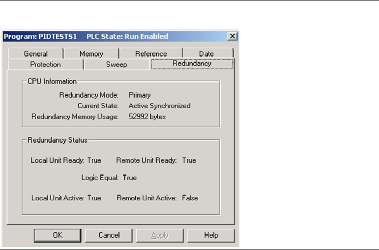
PACSystems™ RX3i Hot Standby CPU Redundancy User Manual Section 5
GFK-2308W May 2021
Configuration Requirements 79
Transfer List
Use this tab to select the ranges of references that will be transferred from the Active
unit to the Backup unit. If the program logic requires identical input values for the
two units, those references must be included in the input transfer list.
A maximum of 2 Mbytes of data can be included in the transfer list. The amount of
data transferred is also limited by the amount of user memory consumption.
Overrides and Legacy-style Transitions are transferred for any specified discrete
transfer data, as well as point fault information for transferred discrete and analog
data if Point Faults are enabled. Transferred data, along with user program,
configuration, and reference memory size, etc. all count against the user memory
size and contributes to the CPU scan time.
Because the redundancy transfer list is part of hardware configuration, the transfer
lists in both units must be the same for synchronization to occur.
Note: Individual variables can also be configured as transferred variables in either or
both the input and output transfer lists. For details, refer to the Section 5.5, Adding
Individual Variables to the Transfer Lists.
To view the amount of memory used for transfer data (redundancy memory usage),
go online and store the configuration. Then right click the Target, choose Online
Commands, and select Show Status. In the status dialog box, select the Redundancy
tab.
Figure 31: Display of Redundancy Memory Usage

PACSystems™ RX3i Hot Standby CPU Redundancy User Manual Section 5
GFK-2308W May 2021
Configuration Requirements 80
Parameter
Default
Choices
Description
Input/Output Transfer Point
%I
Reference
%I00001
This address must be byte-aligned,
that is, it must have a value of 8n + 1.
Example: %I00025
where 25= (8 × 3) + 1.
The starting address for the range of %I references
that are synchronized between the redundant CPUs.
%I Length
0
0 through (32,768 - Iref + 1), in
increments of 8, where Iref = the value
set in the %I Reference parameter.
The number of %I references that are synchronized
between the redundant CPUs.
%Q
Reference
%Q00001
This address must be byte-aligned,
that is, it must have a value of 8n + 1.
Example: %Q00049,
where 49 = (8 × 6) + 1.
The starting address for the range of %Q references
that are synchronized between the redundant CPUs.
%Q Length
0
0 through (32,768 - Qref + 1), in
increments of 8, where Qref = the
value set in the % Q Reference
parameter.
The number of %Q references that are synchronized
between the redundant CPUs.
%M
Reference
%M00001
This address must be byte-aligned,
that is, it must have a value of 8n + 1.
Example: %M00121,
where 121 = (8 × 15) + 1.
The starting address for the range of %M references
that are synchronized between the redundant CPUs.
%M Length
0
0 through (32,768 - Mref + 1), in
increments of 8, where
Mref = the value set in the % M
Reference parameter.
The number of %M references that are synchronized
between the redundant CPUs.
%G
Reference
%G00001
This address must be byte-aligned,
that is, it must have a value of 8n + 1.
Example: %G00081,
where 81 = (8 × 10) + 1.
The starting address for the range of %G references
that are synchronized between the redundant CPUs.
%G Length
0
0 through (7,680 - Gref + 1), in
increments of 8, where Gref = the
value set in the % G Reference
parameter.
The number of %G references that are synchronized
between the redundant CPUs
%AI
Reference
%AI00001
The limit configured for %AI references
is based on values provided in the
Memory tab. The value of the
beginning references plus the value of
the length must be less than, or equal
to, the configured limit.
The starting address for the range of %AI references
that are synchronized between the redundant CPUs.
%AI Length
0
0 through (AIul - AIref + 1), where AIul
= the upper limit of %AI memory
configured on the Memory tab, and
AIref = the value set in the %AI
Reference parameter.
The number of %AI references that are synchronized
between the redundant CPUs.
%AQ
Reference
%AQ00001
The limit configured for %AQ
references is based on values provided
in the Memory tab. The value of the
beginning reference address plus the
value of the length must be less than,
or equal to, the configured limit.
The starting address for the range of %AQ references
that are synchronized between the redundant CPUs.

PACSystems™ RX3i Hot Standby CPU Redundancy User Manual Section 5
GFK-2308W May 2021
Configuration Requirements 81
Parameter
Default
Choices
Description
%AQ
Length
0
0 through (AQul - AQref + 1), where
AQul = the upper limit of %AQ memory
configured on the Memory tab, and
AQref = the value set in the % AQ
Reference parameter.
The number of %AQ reference addresses that are
synchronized between the redundant CPUs. The
limit configured for %AQ references is based on
values provided in the Memory tab. The value of the
beginning reference plus the value of the length
must be less than, or equal to, the configured limit.
%R
Reference
%R00001
The limit configured for %R references
is based on values provided in the
Memory tab. The value of the
beginning references plus the value of
the length must be less than, or equal
to, the configured limit.
The starting address for the range of %R references
that are synchronized between the redundant CPUs.
%R Length
0
0 through (Rul - Rref + 1), where Rul =
the upper limit of %R memory
configured on the Memory tab, and
Rref = the value set in the %R Reference
parameter.
The number of %R reference addresses that are
synchronized between the redundant CPUs. The
limit configured for %R references is based on values
provided in the Memory tab. The value of the
beginning address plus the value of the length must
be less than, or equal to, the configured limit.
%W
Reference
%W00001
The limit configured for %W references
is based on values provided in the
Memory tab. The value of the
beginning reference address plus the
value of the length must be less than,
or equal to, the configured limit.
The starting address for the range of %W references
that are synchronized between the redundant CPUs.
%W Length
0
0 through (Wul - Wref + 1), where Wul
= the upper limit of %W memory
configured on the Memory tab, and
Wref = the value set in the %W
Reference parameter.
The number of %W references that are synchronized
between the redundant CPUs. The limit configured
for %W references is based on values provided in the
Memory tab. The value of the beginning reference
address plus the value of the length must be less
than, or equal to, the configured limit.
Genius HSB
If the program logic requires identical input values for the two units, those references
(including Genius inputs) must be included in the input transfer list.
You must include all redundant Genius outputs, (that is, those %Q and %AQ
references tied to redundant Genius devices, in the output transfer list). Failure to do
so will result in the Primary CPU always determining the output values, even when it
is the Backup unit.
By default, Machine Edition generates an error and prevents storing of the
configuration if a redundant output is not included in the transfer list. For special
situations, you can adjust the Target property, Genius Output, to generate a warning
instead.
Note: In an RX3i CPU Redundancy system, when a GBC is configured as Redundant
Controller External, all its outputs are redundant.

PACSystems™ RX3i Hot Standby CPU Redundancy User Manual Section 5
GFK-2308W May 2021
Configuration Requirements 82
5.4.3 Redundancy Memory Xchange Module Parameters
Table 10: Redundancy Memory Xchange Module Parameters
Parameter
Default
Choices
Description
Redundancy
Link
Enabled
Enabled
Disabled
If the RMX module is being used as a redundancy link,
this parameter must be set to Enabled. An RMX module
being used as a redundancy link cannot be used as a
general-purpose reflective memory module. All the
reflective memory parameters are unavailable, and the
Interrupt parameter is set to Disabled.
5.4.4 Ethernet Interface Parameters
Each unit contains at least one Ethernet interface that is assigned a direct IP address
used to directly access the specific unit. A third, redundant, IP address can be
assigned to the pair of Ethernet interfaces in both the Primary and Secondary CPUs.
The redundant IP address is active on the Ethernet interface in only one of the units at
a time, the Active unit. All data sent to the redundant IP address (including EGD
produced to the redundant IP address) is handled by the Active unit. When active, the
Ethernet interface always initiates communications using the redundant IP address.
(EGD production is the only exception. EGD production can be configured to use
either the direct or redundant IP address as the source IP address.) When the unit is
not active, all communications are initiated through the direct IP address. For more
information about the Redundant IP address, refer to Section 6.16, Redundant IP
Addresses.
You can have up to four Ethernet interfaces in each rack, including the embedded
Ethernet interface in an CPU. Each Ethernet interface can be set up as part of a pair for
the purposes of redundant IP. (You can also include Ethernet interfaces in the unit
that are not part of a redundant IP pair.)
When an Ethernet Interface is configured to produce Ethernet Global Data (EGD), you
must configure a redundant IP address in addition to the direct IP address. For more
information about using EGD in a redundancy system, refer to Section 6: Operation.

PACSystems™ RX3i Hot Standby CPU Redundancy User Manual Section 5
GFK-2308W May 2021
Configuration Requirements 83
Table 11: Ethernet Interface Parameter Definitions
Parameter
Default
Choices
Description
IP Address
0.0.0.0
x.x.x.x where x
ranges from
1 to 255
This IP address, also known as the direct IP address,
always applies only to this unit. The IP Address should be
assigned by the person responsible for your network.
TCP/IP network administrators are familiar with these
sorts of parameters and can assign values that work with
your existing network. If the IP address is improperly set,
your device might not be able to communicate on the
network and could disrupt network communications.
Redundant IP
Disable
Disable
Enable
Enabling this feature allows the Ethernet Interface to
share an IP address with the corresponding Ethernet
Interface in the other unit. When this parameter is
enabled, a Redundant IP Address must be entered.
Redundant IP
Address
0.0.0.0
x.x.x.x where x
ranges from
1 to 255
(Available only when the Redundant IP parameter is set
to Enable.) The IP address shared by two Ethernet
Interfaces that are connected to the same network and
reside in separate units (one in the Primary CPU and the
other in the Secondary CPU). Although the redundant IP
address is shared by both Ethernet Interfaces, only the
Interface in the Active unit responds to this IP address.
This IP address is assigned in addition to the device’s
Primary IP address.
The redundant IP address must not be the same as the
direct IP address of either Ethernet Interface. The
redundant IP address must be on the same sub-network
as the direct IP address and Gateway IP Address, if used.
For more information about Ethernet redundancy, refer
to the PACSystems RX3i and RSTi-EP TCP/IP Ethernet
Communications User Manual, GFK-2224.
Produce EGD on
Redundant IP
False
False
True
When this feature is enabled (True) the active unit will
produce EGD using the redundant IP address as the
source IP address. When this feature is disabled (False)
the active unit will produce EGD using the direct IP
address.
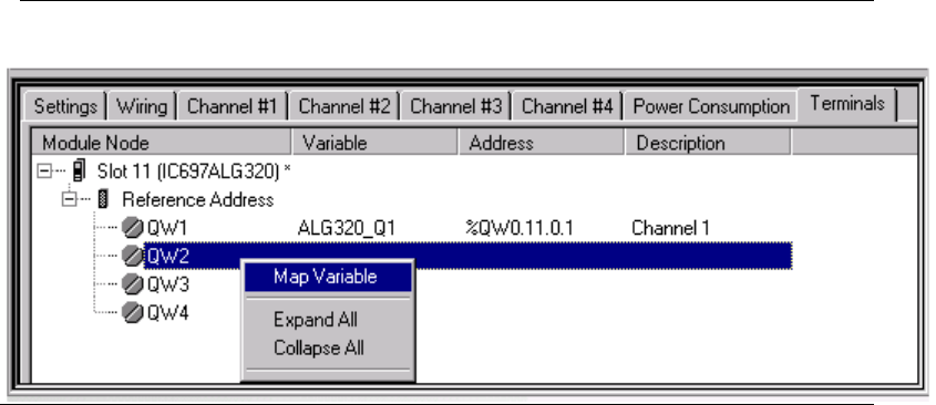
PACSystems™ RX3i Hot Standby CPU Redundancy User Manual Section 5
GFK-2308W May 2021
Configuration Requirements 84
5.4.5 Rack Module Configuration Parameters
I/O Interrupts
Interrupts cannot be ENABLED when the configured CPU is a Redundant CPU. When a
redundant CPU is configured, any interrupts enabled in the configuration are
DISABLED.
I/O Variables
An I/O variable is a symbolic variable that is mapped to a terminal in the hardware
configuration for individual modules. A terminal can be one of the following: a
physical discrete or analog I/O point on a PACSystems module or on a Genius device,
a discrete or analog status returned from a PACSystems module, or Global Data. The
use of I/O variables allows you to configure hardware modules without having to
specify the reference addresses to use when scanning their inputs and outputs.
Instead, you can directly associate variable names with a module’s inputs and
outputs.
I/O variables can be used any place that other symbolic variables are supported, such
as in logic as parameters to built-in function blocks, user-defined function blocks,
parameterized function blocks, C blocks, bit-in-word references, and transitional
contacts and coils. For additional information on the use of I/O variables, refer to the
PACSystems RX3i and RSTi-EP CPU Reference Manual, GFK-2222.
Figure 32: Example of Mapping Hardware I/O Variables
Using I/O Variables in a Redundancy System
In a redundancy system, the mapping of I/O variables must be the same in both units.
It is possible to have different modules configured in each unit, as long as the
modules that differ do not have I/O variables assigned to them.
When an I/O variable is added, moved or deleted in one hardware configuration,
Machine Edition performs the same action on the other hardware configuration. If
you move a module with I/O variables to a different rack location, the variables in the
corresponding module in the other hardware configuration are disassociated,
PACSystems™ RX3i Hot Standby CPU Redundancy User Manual Section 5
GFK-2308W May 2021
Configuration Requirements 85
causing an I/O Variable Mismatch error. If an I/O variable is assigned to a module in
one unit without a corresponding I/O variable on a module of the same type in the
other unit, an I/O Variable Mismatch error will be generated upon validation.
I/O variables can be configured as transferred variables in either or both the input and
output transfer lists. For details, refer to Section 5.5, Adding Individual Variables to the
Transfer Lists.
5.4.6 Genius Bus Configuration
Bus Controller Configuration Parameters
When configuring the PRIMARY controller, all GBCs configured for external
redundancy must have Serial Bus Address 31.
When configuring the SECONDARY controller, all GBCs configured for external
redundancy1 must have Serial Bus Address 30.
Note: It is possible to configure Genius networks in which there is not a redundant
bus controller in the other unit. For such networks, the serial bus addresses do
notneed to be 31 in the Primary CPU system and 30 in the Secondary CPU system.
For single Genius bus networks in targets, the GBCs’ Redundancy Mode parameter
must be configured for Redundant Controller with the redundant pair set to External.
For single Genius bus networks in RX3i targets, the GBCs’ Redundancy Mode
parameter must be configured for Redundant Controller - External.
For Dual Bus Genius networks in targets, the GBCs must be configured for Dual
Bus/Redundant Controller.
For Dual Bus Genius networks in RX3i targets, the GBCs must be configured for
Redundant Controller - External.
Note: Dual Bus Genius networks in RX3i targets need to be configured manually, and
%I and %AI references on Genius bus B must have offsets. The %I offset is 10000 and
the %AI offset is 5000.
Note: GBCs for networks that are connected to just one unit can have any setting.
Genius Device Configuration Parameters
All Genius devices that are connected to both units must be configured as redundant.
Note: Devices that are connected to just one unit can use any available setting.
Note: In an RX3i CPU Redundancy System, when a GBC is configured as Redundant
Controller – External, all its outputs are redundant.
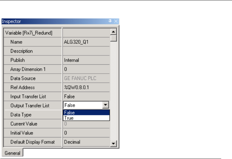
PACSystems™ RX3i Hot Standby CPU Redundancy User Manual Section 5
GFK-2308W May 2021
Configuration Requirements 86
5.5 Adding Individual Variables to the Transfer
Lists
Individual variables can be configured as transferred variables in the input transfer list
and/or the output transfer list. Mapped, managed (symbolic and I/O), and function
block instance variables can be transferred. This is the only way that managed and
function block instance variables can be transferred.
The following types of variables cannot be transferred:
• Mapped BOOL variables with bit-in-word addresses
• Elements of BOOL arrays that are mapped to word memories (%R, %W, %AI,
% AQ)
• Aliases to variables
The Input Transfer List and Output Transfer List properties for a variable are set to
False by default.
In most cases, a variable should be part of the input or output transfer, but not both.
In some unusual cases, where there is a need to update a variable at both transfer
points in the sweep, the variable can be configured for both lists.
Figure 33: Configuration for Including a Variable in the Transfer List

PACSystems™ RX3i Hot Standby CPU Redundancy User Manual Section 5
GFK-2308W May 2021
Configuration Requirements 87
5.5.1 Mapped Variables
An advantage of configuring mapped variables this way instead of including them in the CPU’s Transfer List is
that the transfer properties are tied to the variable, not the memory location. If you need to relocate a
variable, you do not risk accidentally moving it out of the transfer area.
Mapped variables must be assigned to one of the memory ranges allowed for redundancy transfer: %I, %AI,
%Q, %AQ, %R, %M, %W, or %G.
Note: If a mapped variable within a range specified in the CPU hardware configuration Transfer
List is also configured as a transferred variable, it will be transferred twice.
5.5.2 Arrays
Arrays can be configured as Mixed transferred variables, allowing individual elements
to be included in the input transfer list and/or the output transfer list. If the top level
of the array variable is set to True or False for either list, all elements in the array are
set to the top-level value for that list.
5.5.3 Instance Data Structure Variables
All elements of instance data structure variables, such as those associated with a
function block, are transferred according to the setting of the head of the data
structure.
5.5.4 Using the Variable Transfer List Report
The report provides the total number of variable bytes, the total whole bytes, and the
total partial bytes included in the input and the output transfer lists.
To access this report, right-click the Target and select Report. In the Available Reports
list, select Variable Transfer List Report and click OK.
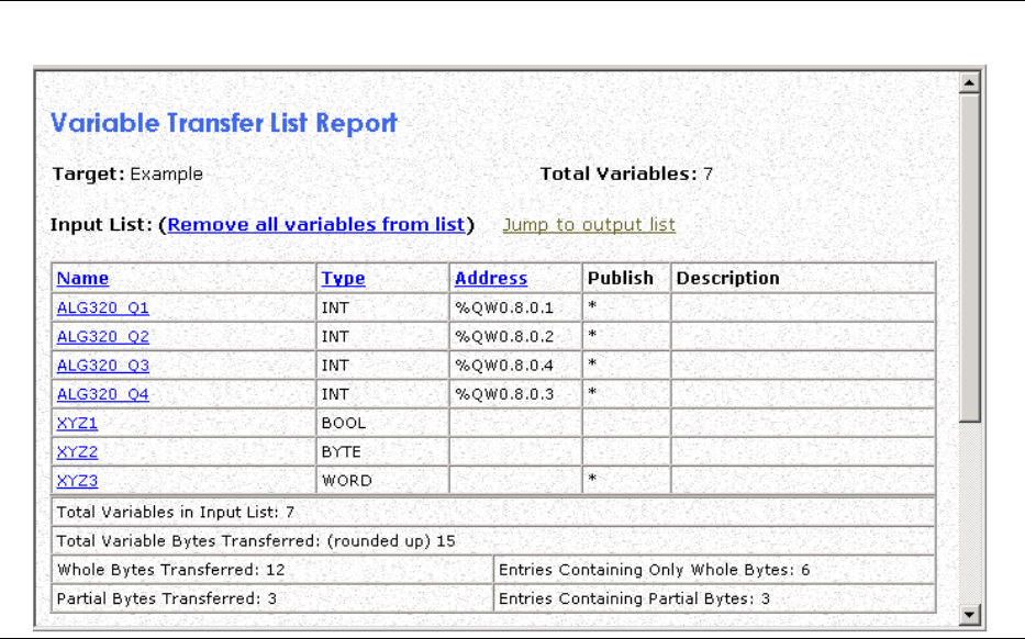
PACSystems™ RX3i Hot Standby CPU Redundancy User Manual Section 5
GFK-2308W May 2021
Configuration Requirements 88
Figure 34: Variable Transfer List Report
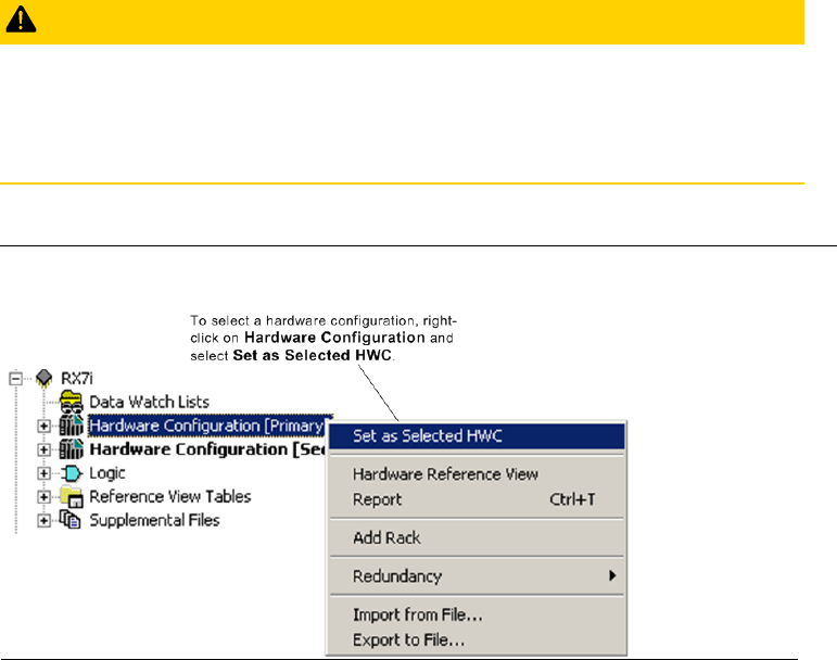
PACSystems™ RX3i Hot Standby CPU Redundancy User Manual Section 5
GFK-2308W May 2021
Configuration Requirements 89
5.6 Storing (Downloading) Hardware
Configuration
A PACSystems control system is configured by creating a configuration file in the
programming software, then transferring (downloading) the file from the
programmer to the CPU through the Ethernet Interface or serial port. The CPU stores
the configuration file in its non-volatile RAM memory.
In the programming software all online operations, including downloading a folder,
are performed on the controller that is the selected hardware configuration. You
must download the hardware configuration to each controller in the redundancy
system in a separate operation.
CAUTION
If both units are configured as Primary or as Secondary, they will not recognize one
another. GBCs only blink their LEDS and no fault will be reported.
Correct the configuration of both units before placing either unit in Run mode.
1. Make sure the Primary HWC is selected (Figure 35).
Figure 35: Select Primary Controller as Target
2. If not already done, set the physical port parameters for the Primary CPU in the
Target properties.
3. Connect to the CPU. Make sure the CPU is in Stop mode.
4. Download.
5. Go offline.
6. Select the Secondary HWC.
7. If not already done, set the physical port parameters for the Secondary CPU in
the Target properties.
8. Connect to the CPU. Make sure the CPU is in Stop mode.
9. Download.

PACSystems™ RX3i Hot Standby CPU Redundancy User Manual Section 5
GFK-2308W May 2021
Configuration Requirements 90
5.7 Run Mode Store
PACSystems releases 5.5 and later supports Run Mode Store (RMS) of the redundancy
transfer list. This capability allows you to add, delete or modify transfer list entries
without stopping the controllers.
If two redundant units are synchronized, the RMS must be performed as a dual
operation. However, when a redundant unit is not synchronized to another unit, the
redundancy transfer list can be stored in a single RMS. This facilitates the
commissioning phase of a redundancy system, where the redundant partner might
not be in place yet.
CAUTION
Do not attempt to synchronize a unit while an RMS is in progress to a non-
synchronized Active unit. If the unit attempting to synchronize in this case is taken to
run mode, both units will be non-synchronized Active units. For systems that contain
redundantly controlled PROFINET I/O, when both units become non-synchronized
Active units, the unit that was the synchronized Active unit will then go to Stop mode.
An RMS of the transfer list requires two copies of the redundancy configuration to be
resident on the controller for a short time. During that period both copies of the
transfer list are charged against the user memory limit. If there is not enough user
space available for both copies (along with any new logic or EGD data that is part of
the RMS), the store will fail.
5.7.1 Dual RMS with Simultaneous Activation in Redundant
Systems
WARNING
A synchronous RMS of invalid user logic or configuration, such as would cause a
watchdog or processor exception, could cause both units to fail. To mitigate the risk
of such application errors, the procedure, Initial RMS Followed by Dual RM on the
following page is recommended.
To modify EGD, application logic, and/or the redundancy transfer list using RMS and
have the controllers simultaneously activate the changes, you must perform
independent downloads to both controllers. The two controllers then negotiate
when to activate the new items. The initial store can be done to either the Primary or
the Secondary CPU. Note that a dual RMS does not have to include transfer lists. It
could include only EGD and/or logic.
When you command an RMS to one of the units, you will be given the option of
selecting synchronized activation of the redundant controllers.
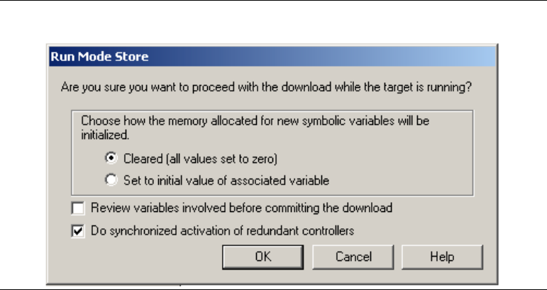
PACSystems™ RX3i Hot Standby CPU Redundancy User Manual Section 5
GFK-2308W May 2021
Configuration Requirements 91
Figure 36: Run Mode Store
If you select Do synchronized activation of redundant controllers, the first unit defers
application of the newly stored application data until the following actions have
occurred:
10. You disconnect from the first unit, connect to the other unit, and command an
RMS to that unit.
11. The programmer performs the RMS to the second unit.
12. Both units validate that the new application data is compatible in the two units.
Because the controller sweeps are synchronized, both units will activate the
new logic and transfer lists on the same sweep.
If a power loss occurs on one of the units after activation of the new components
begins, but before it completes, the unit maintaining power will complete the
activation and continue as a non-synchronized Active unit. When the other unit is
powered back on (assuming a good battery) it will either have the newly stored
application or the original application. If the units match, they can synchronize
without a download. If the unit that lost power does not contain the new application
data, a Primary and Secondary CPUs are incompatible fault (fault 9 in group 138) will
be generated.
5.7.2 Initial RMS Followed by Dual RMS
The following procedure is recommended to avoid the risk of both units failing due to
logic errors in a dual RMS:
1. Perform an RMS of the new application data only to the Backup controller prior
to modifying the transfer list. (Do synchronized activation of redundant
controllers is not selected.)
2. Perform a role switch to make the modified controller Active.
3. Add any variables that require synchronization to the transfer list. (Refer to 5.5,
Adding Individual Variables to the Transfer Lists.)
4. Initiate a dual RMS.

PACSystems™ RX3i Hot Standby CPU Redundancy User Manual Section 5
GFK-2308W May 2021
Configuration Requirements 92
5. If necessary, perform a role switch so that the Primary CPU is the Active unit.
The unit whose logic had already been stored in run mode will receive only the
new transfer list. The other unit will receive the new transfer list and new
logic/EGD.
5.7.3 RMS Operational Errors
Certain operational errors can occur only when performing a dual RMS to two
synchronized controllers and performing simultaneous activation of new application
data. The table below outlines possible modes of failure and the system operation
when the failure occurs.
Table 12: RMS Operational Errors
Error Mode
System Operation
User requests a normal store (single RMS,
not dual RMS) when the transfer list has
changed.
The programmer will not attempt the run mode store and will display an
error message.
User requests a dual RMS on a controller
that is not synchronized to a redundant
partner.
The dual store will not be completed. The programmer will display the
following controller error message:
The requested action could not be completed because the target is not
synchronized with another controller. (0x05, 0x3E)
User requests a dual RMS on a controller
whose redundant partner does not
support dual RMS.
The dual store will not be completed. The programmer will display the
following controller error message:
The firmware for the remote redundant controller does not support the
operation. (0x05, 0x3C)
Dual RMS aborted (user commanded, loss
of communications, failed download) to a
controller whose redundant partner does
not have a pending dual RMS.
The controller will abort the RMS and delete any new application data that
had been stored.
Dual RMS aborted (user commanded, loss
of communications, failed download) to a
controller whose redundant partner has a
pending dual RMS.
Both controllers will abort the RMS and delete any new application data
that had been stored.
Loss of synchronization in a dual RMS
where only one controller has a pending
dual RMS.
The controller will abort the RMS and delete any new application data that
had been stored.
Loss of synchronization in a dual RMS
where both controllers have a pending
dual RMS.
Both controllers will abort the RMS and delete any new application data
that had been stored.

PACSystems™ RX3i Hot Standby CPU Redundancy User Manual Section 5
GFK-2308W May 2021
Configuration Requirements 93
Error Mode
System Operation
The two controllers determine that the
newly stored transfer lists are not
compatible.
Both controllers will abort the RMS and delete any new application data
that had been stored.
One or both of the units determine that
there is a problem with one of the
components downloaded during the run
mode store.
Both controllers will abort the RMS and delete any new application data
that had been stored.
A loss of synchronization occurs after the
activation of the new components begins,
but before it completes.
Both units complete the activation of newly stored application data and
run as non-synchronized Active units
10
.
A fatal error (stop halt) occurs after the
activation of the new components begins,
but before it completes.
Both units complete the activation of newly stored application data. If only
one unit has a fatal error, the other unit will run as a non-synchronized
Active unit.
A power loss occurs on one of the units
after activation of the new components
begins, but before it completes.
The unit maintaining power will complete the activation and continue as a
non-synchronized Active unit. If the other unit is powered back on
(assuming a good battery) it will either have the newly stored application
or the original. The firmware will attempt to ensure that this unit has the
new application so that it can synchronize to the other unit without a
download, but it will not be guaranteed.
If the units match, they can synchronize without a download. If the unit
that lost power does not contain the new application data, a Primary and
Secondary CPUs are incompatible fault (fault 9 in group 138) will be
generated.
User attempts to go to programmer mode
on a controller that already has a pending
dual RMS.
You will be prompted to either abort the dual RMS or stay in monitor
mode.
User requests a role switch via logic or the
physical switch on the RMX module.
User commanded role switches do not impact the ability to do a dual RMS.
The role switch could be deferred for a maximum of one sweep if it
coincides with the simultaneous activation.
Dual RMS could fail in Normal sweep mode
with the Backplane Communication
Window Mode set to Complete.
Synchronization is lost and both units
transition to NSAU operation.
10
When RMS of a large file is performed with the CPU in this sweep mode,
the CPU tries to complete the RMS in a single scan, causing the sweep time
to exceed the Fail Wait Time.
To avoid this failure, set the Backplane Communication Window Mode to
Limited or select the Constant Window or Constant Sweep mode.
10
For systems that contain redundantly controlled PROFINET I/O, when both units become non-
synchronized Active units, the unit that was the synchronized Active unit will go to Stop mode.
PACSystems™ RX3i Hot Standby CPU Redundancy User Manual Section 5
GFK-2308W May 2021
Configuration Requirements 94
5.7.4 Behavior of EGD in a Dual RMS
Added exchanges will begin consumption/production shortly after the activation of
logic that is part of the RMS. Deleted exchanges will cease consumption/production
shortly before the activation of logic that is part of the RMS. Modified exchanges will
be offline for a short time during the activation of new logic that is part of the RMS.
For general information about the behavior of this feature in a simplex system, refer
to the PACSystems RX3i and RSTi-EP TCP/IP Ethernet Communications User Manual, GFK-
2224, to the section, Run Mode Store of EGD.
Unlike activation of the transfer list and logic, activation of EGD changes is not
guaranteed to be simultaneous between the two units in a dual RMS. Even in cases
where hardware configuration and logic are identical on the two units, it cannot be
guaranteed that production/consumption of deleted or modified exchanges will stop
on the same controller sweep. Likewise, it cannot be guaranteed that
production/consumption of added or modified exchanges will resume on the same
controller sweep. This is consistent with normal operation of EGD in a redundancy
system.
5.7.5 Hardware Configuration and Logic Coupling
If I/O Variables are used, an RMS must include both logic and hardware configuration.
If I/O Variables are not used, you can choose whether to RMS logic, hardware
configuration, or both. If you choose hardware configuration or both, all portions of
hardware configuration that can be stored in run mode will be included. If there are
portions of hardware configuration that are not equal and cannot be stored in run
mode, a warning will be generated.
PACSystems™ RX3i Hot Standby CPU Redundancy User Manual Section 6
GFK-2308W May 2021
Operation 95
Section 6: Operation
This chapter discusses aspects of PACSystems CPU operation that function differently
in a redundancy system. For general details of CPU operation, refer to the PACSystems
RX3i and RSTi-EP CPU Reference Manual, GFK-2222.
▪ Power-up of a Redundant CPU
▪ Synchronizing Redundant CPUs
▪ %S References for CPU Redundancy
▪ Scan Synchronization
▪ Fail Wait Time
▪ Data Transfer
▪ Switching Control to the Backup Unit
▪ STOP to RUN Mode Transition
▪ RUN with Outputs Disabled Mode
▪ RUN to STOP Mode Transition
▪ Error Checking and Correction
▪ Timer and PID Functions
▪ Timed Contacts
▪ Multiple I/O Scan Sets
▪ Genius Bus Controller Switching
▪ Redundant IP Addresses
▪ Ethernet Global Data in an HSB Redundancy System
6.1 Power-up of a Redundant CPU
When a redundant CPU is powered up, it performs a complete hardware diagnostic
check and a complete check of the application program and configuration
parameters. This causes the power-up time of a redundant CPU to be longer than
that of a non-redundant CPU.
If the Primary and Secondary CPUs power up together, the Primary becomes the
Active unit and the Secondary CPU becomes the Backup unit. Whenever the
Secondary CPU powers up and does not detect the Primary CPU, the Secondary CPU
waits for a specific period for the Primary CPU to power up. If the Primary CPU has not

PACSystems™ RX3i Hot Standby CPU Redundancy User Manual Section 6
GFK-2308W May 2021
Operation 96
completed its power-up sequence within the specified time, the Secondary CPU
assumes that the Primary CPU is not present. In this case, if the Secondary CPU is
configured to transition to Run on power-up, it becomes an Active unit without a
Backup unit.
If the Primary CPU completes its power-up sequence before the Secondary CPU, the
Primary CPU waits a few seconds for the Secondary CPU to complete its power-up
sequence. If the Primary CPU is set up to transition to Run on power-up and does not
detect the Secondary CPU within this time, it becomes an Active unit without a
Backup.
Power-up times vary from one CPU model to another, so the Secondary CPU power-
up wait time is adjusted accordingly:
Table 13: Secondary CPU Power-up Wait Time
CPU Model
Secondary CPU Power-up Wait Time
CPE330
70 seconds
CPE400
70 seconds
CPL410
70 seconds
All other Redundant CPUs
30 seconds
Note: If the entire system should be fully redundant upon power-up, the Secondary
CPU must complete power-up before the Primary CPU powers up, but must do so
with the time indicated. To ensure this, apply power to the Secondary CPU before
applying power to the Primary.
If either unit is powered up after the other unit is already in Run mode,
communications between the two units are established. If the unit is powered up
goes to Run mode, a resynchronization occurs (refer to Section 6.2).
6.1.1 Synchronizing the Time of Day Clocks
At the point when the two units establish communications through the redundancy
link(s), the Primary CPU’s time of day clock is copied to the Secondary CPU.
PACSystems™ RX3i Hot Standby CPU Redundancy User Manual Section 6
GFK-2308W May 2021
Operation 97
6.1.2 Validity of PROFINET I/O at Power-up
When a PACSystems controller returns to service after a power outage, it can take
several seconds for that controller’s PNCs to come online and for each PNC to bring
its configured IO devices online. The CPU does not prevent itself from going into RUN
mode while it is in the process of bringing the PROFINET IO online. Because a
PACSystems CPU can go to RUN mode before its IO devices are ready, you should be
aware of the following.
Inputs and Input Point Faults
When a redundantly-controlled PROFINET I/O device is not online with the Active unit,
the Active CPU sets that device’s inputs to the default values and sets the
corresponding input point faults to the faulted state. At power-up, these inputs and
input point faults will remain in this state until that I/O device comes online and starts
transferring inputs to the PNC in the Active unit,
When a simplex PROFINET I/O device is not online, the CPU for which that device is
configured will set that device’s inputs to the default values and set the
corresponding input point faults to the faulted state. At power-up, these inputs and
input point faults will remain in this state until that I/O device comes online and starts
transferring inputs to corresponding PNC.
Therefore, if the control application needs to know whether a set of PROFINET inputs
is valid or not, it must refer to the input point faults.
Output Point Faults
Whenever a simplex PROFINET I/O device is not online, the CPU for which that device
is configured for will set the output point faults for that device to the faulted state.
However, the Hot Standby CPUs do not support use of the output points faults
associated with redundantly-controlled PROFINET I/O devices. Thus, the application
should not use the point faults that correspond to redundantly-controlled PROFINET
outputs.
Additional information on operation at a STOP-RUN transition can be found in
Section 6.8, STOP to RUN Mode Transition.
6.2 Synchronizing Redundant CPUs
When synchronization is initiated, the CPUs exchange information about their
configurations. If a transitioning CPU detects that the configurations are not in
agreement, that CPU will not transition to RUN mode; if both CPUs are transitioning
at the same time, neither CPU transitions to RUN mode.
The following items must be in agreement in order to synchronize:
1. Both CPUs must be configured for the same redundancy control strategy.
2. Both CPUs must have identical transfer lists.
3. If %I, %Q, %AI, or %AQ references are included in the transfer list, the Point Fault
References configuration parameter must be identical on both units.
PACSystems™ RX3i Hot Standby CPU Redundancy User Manual Section 6
GFK-2308W May 2021
Operation 98
During synchronization, the Active unit sends a synchronization request to the
Backup unit and waits for a response from the Backup unit. If the Active unit does not
receive a response from the Backup unit within its configured Fail Wait Time, it
operates as a non-synchronized Active unit (NSAU).
During synchronization, the Backup unit waits for a synchronization request from the
Active unit. If the Backup unit does not receive the request within its configured Fail
Wait Time, it transitions to NSAU operation. If the Backup unit receives a
synchronization request within the Fail Wait Time, it waits to receive the
synchronization data. If it receives the data within 60ms, synchronization completes.
If it does not receive the data, the Backup unit operates as a NSAU.
6.2.1 Dual Synchronization
Dual Synchronization occurs when both CPUs transition to Run at the same time. The
Primary CPU becomes the Active unit and the Secondary CPU becomes the Backup
unit.
Non-retentive data is cleared, and the #FST_SCN reference and #FST_EXE bits are set
to 1.
Note: Because CPE330 supports a CRU320 compatibility mode (which allows a
CRU320 configuration to be downloaded to a CPE330) a mixed-model CPU system
can be created. In a mixed-model system, Dual Synchronization at power-up cannot
be guaranteed because of the power-up time differences of the two CPUs. It is not
recommended to design a system with mixed-models; however, this setup can be
used to replace a failed redundant CPU.
6.2.2 Resynchronization
Resynchronization occurs when one unit is already in Run mode and the other unit is
put into Run mode. The unit already in RUN mode remains the Active unit and the
transitioning unit becomes the Backup unit. The behavior is the same whether the
unit going to RUN is the Primary CPU or the Secondary CPU.
At this point, the Active unit sends the output transfer data and the input transfer
data to the Backup unit. In addition to the configured redundancy transfer data, the
#FST_SCN % S reference as well as internal timer information and #FST_EXE for each
common logic block are transferred from the Active unit to the Backup unit. Only the
internal timers and #FST_EXE data for program blocks with the same name are
transferred. Therefore, the #FST_SCN and #FST_EXE bits for common blocks are not
set on the first scan of the transitioning unit.
6.2.3 Operation when a Redundancy Link is Removed
When one of the links in a system with dual redundancy links is lost, for example
when the fiber-optic cable is removed from one RMX module, and the CPUs remain
synchronized with one link, the redundancy status LEDs (Local Ready, Local Active,
Remote Ready, Remote Active) on the RMX modules associated with the failed link
will continue to be updated.

PACSystems™ RX3i Hot Standby CPU Redundancy User Manual Section 6
GFK-2308W May 2021
Operation 99
6.3 %S References for CPU Redundancy
%S33 through %S39 and %SB18 reflect the status of the redundancy units. The table
below describes these %S references, and shows their expected states, assuming the
Primary CPU is Active and the Secondary CPU is Backup.
Table 14: %S Bit Definitions
%S Bit
Definition
Name
Description
Expected State
Primary
CPU
Secondary
CPU
%S33
Primary CPU
#PRI_UNT
Set to 1 if the local unit is configured as the
Primary CPU. Otherwise it is set to 0. For any
given local unit, if PRI_UNT is set, SEC_UNT
cannot be set.
ON
OFF
%S34
Secondary CPU
#SEC_UNT
Set to 1 if the local unit is configured as the
Secondary CPU. Otherwise it is set to 0. For any
given local unit, if SEC_UNT is set, PRI_ UNT
cannot be set.
OFF
ON
%S35
Local Unit Ready
#LOC_RDY
Set to 1 if local unit is in Run mode with outputs
enabled. Otherwise it is set to 0.
ON
ON
%S36
Local Unit Active
#LOC_ACT
Set to 1 if local unit is currently the Active unit.
Otherwise it is set to 0. For any given local unit,
if LOC_ACT is set, REM_ACT cannot be set.
ON
OFF
%S37
Remote Unit Ready
#REM_RDY
Set to 1 if remote unit is in Run mode with
outputs enabled. Otherwise it is set to 0.
ON
ON
%S38
Remote Unit Active
#REM_ACT
Set to 1 if remote unit is currently the Active
unit. Otherwise it is set to 0. For any given local
unit, if REM_ACT is set, LOC_ACT cannot be set.
OFF
ON
%S39
Logic Equal
#LOGICEQ
Set to 1 if the application logic for both units in
the redundant system is the same. Otherwise it
is set to 0.
ON
ON
%S41
Redundancy
Communication
Available
#RDNCOMM
Set to 1 whenever the Redundancy
Communications Interface has at least one
Ethernet Link up.
ON
ON
%S42
Redundancy Link 1 OK
#RDNP1LINK
Set to 1 whenever Redundancy Ethernet Port 1
has link on its PHY.
ON
ON
%S43
Redundancy Link 2 OK
#RDNP2LINK
Set to 1 whenever Redundancy Ethernet Port 2
has link on its PHY.
ON
ON
%SB18
Redundancy
Informational
Message Logged
#RDN_MSG
Set if a redundancy informational message was logged. It can be
cleared in reference tables, logic, or by clearing the fault tables.

PACSystems™ RX3i Hot Standby CPU Redundancy User Manual Section 6
GFK-2308W May 2021
Operation 100
%S references can be read from the application program, but cannot be altered or
overridden. These references are always OFF when no configuration has been stored.
Anytime a configuration is stored, the states of these %S references are updated in
both STOP and RUN modes.
The four redundancy status LEDs on the RMX Module correspond to the %S35, %S36,
%S37, and %S38 references. The programming software summarizes the state of the
redundancy system on the Redundancy tab of the Show Status dialog box, accessed
from Online commands. Additionally, external indicators can be used to monitor the
state of any status reference.
If the two CPUs are in Run mode but lose synchronization (due to Fail Wait Time set
too short or failure of both redundancy links), both units generally log faults and
proceed as NSAUs. In this case both units attempt to control the process
independently; both units set their #LOC_ACT status to 1, and clear the #REM_RDY,
#REM_ACT, and #LOGICEQ status flags. However, for systems that contain
redundantly controlled PROFINET I/O, when both units become non-synchronized
Active units, the unit that was the synchronized Active unit will go to STOP mode
instead.
Note: The #OVR_PRE reference, %S00011, is not supported by the Redundant CPU
and should not be used.
6.3.1 Redundancy Status Presented as OPC UA Variables
CPUs that support OPC UA present the Redundancy Status information as OPC UA
variables, as described in this section. These OPC UA variables may be used by EFA
and Predix Cloud, or any OPC UA application, to determine which redundant
controller is Active. The application can then decide which redundant controller’s
data to use (the Active one).
The two variables listed below are OPC UA default variables (i.e., they do not need to
be Published) and are located in the OPC UA path /Objects/GE Device
Information/PACSystems RX3i/Controller/.
▪ System Status Bits – This variable is an unsigned 32-bit integer and contains a copy of all of the
redundancy status bits from %S memory (%S33 to %S48). This includes all the standard Redundancy
bits such as #PRI_UNT, #LOC_ACT, #REM_RDY, documented in 6.3 plus #RDNCOMM, #RDNP1LINK,
and #RDNP2LINK, which are bits specific to CPUs with Ethernet-based redundant communications
links (e.g. CPE400/CPL410).
▪ System Local Active – This variable is a Boolean that is based on the state of the #LOC_ACT %S bit. The
#LOC_ACT bit is also included in the “System Status Bits” variable described above. It is presented
here as a separate Boolean to make the determination of the Active CPU unit easier for the OPC UA
application.

PACSystems™ RX3i Hot Standby CPU Redundancy User Manual Section 6
GFK-2308W May 2021
Operation 101
6.4 Scan Synchronization
The figure below shows the sweep components for the Active and the Backup CPUs.
Figure 37: Scan Synchronization Sweep Diagram
There are two synchronization points in the sweep. The input transfer point occurs
immediately after the inputs are scanned. At this point in the sweep, the newly read
inputs are sent from the Active unit to the Backup unit. At the output transfer point,
the rest of the data (outputs, internal references, registers) is sent from the Active
unit to the Backup unit. These data transfers are automatic; they require no
application program logic, but do require proper configuration.
Data can be transferred on either redundancy link. If one link fails, the transfer
switches to the other link without causing a loss of synchronization.
6.4.1 Synchronization of PROFINET I/O
In a Hot Standby CPU Redundancy system, a redundantly controlled PROFINET IO
device exchanges its inputs and outputs with only one of the two controllers that it is
connected to. This transfer occurs with the Active unit. The Backup unit does not
receive inputs directly from, or send outputs directly to, the IO Device because the
Backup unit has a Backup connection with that I/O Device.
Because of this, the programmer requires that all redundantly controlled inputs be
included in the Input Transfer list and all redundantly controlled outputs be included
in the Output Transfer list.
The Active CPU collects the values of the redundantly controlled inputs during its
Input Scan. Whenever the two Hot Standby CPUs are synchronized, the Active unit
sends a copy of those inputs to the Backup unit during the input data transfer. Then
both CPUs execute the logic solution with the same input values. When the logic
solution is complete, the Active unit sends a copy of the redundantly controlled
PROFINET outputs to the Backup unit during the output data transfer. Then both
CPUs provide those outputs to their PNCs during the output scan.
PACSystems™ RX3i Hot Standby CPU Redundancy User Manual Section 6
GFK-2308W May 2021
Operation 102
6.5 Fail Wait Time
The Active and Backup CPUs synchronize their execution twice each sweep: once
before logic execution and once afterwards. Certain failures of one CPU, such as an
infinite loop in the logic, are detected by the other CPU as a failure to reach the next
synchronization point on time. The maximum time to wait for the other CPU is
known as the Fail Wait Time. The duration of this time must be specified during
configuration of both the Primary and Secondary CPUs and can range from 40 ms to
400 ms (in increments of 10 ms), with the default being 60 ms.
The configured Fail Wait Time for the system must be based on the maximum
expected or allowable difference in the two CPUs reaching a synchronization point.
For example, if one CPU might spend 20ms in the communications phase of the
sweep and the other unit might spend 95 ms in communications in the same sweep,
the Fail Wait Time must be set to at least 80 ms (80 > 95 -20) to prevent loss of
synchronization. In addition, Fail Wait Time must be greater than the sum of the
Controller Communications Window, Backplane Communications Window and
Background Window timer settings.
Differences in the logic execution time and other phases must also be considered
when selecting a Fail Wait Time. Some applications limit the possible difference
during the communications window by using Constant Sweep mode or Constant
Window mode, or by setting the system communications window to Limited and
selecting a small window time.
If the Communications Window mode is set to Complete (run to completion), the
controllers could lose synchronization, particularly during RMS using a rack-based
Ethernet module.
6.6 Data Transfer
The data is transferred in blocks. Each block is checked for data integrity. The Backup
CPU holds the transferred data in a temporary area until all the data has been
received and verified. Then the Backup CPU copies the data into the actual controller
memories. If the full transfer fails to complete properly, the Backup unit becomes an
NSAU and discards the data in the temporary area.
6.6.1 Synchronization and Data Transfer Process
Input Data and Synchronization Data Transfer to the Backup
Unit
Immediately after the input scan, the Active unit sends the selected input data to the
Backup unit. This includes the selected ranges within %I, %Q, %AI, %AQ, %R, %M, %G
and %W memories, as well as transferred variables. For discrete data, the status,
override, and legacy-style transition information is transferred. If point faults are
configured, point fault data is also sent.
Sweep Time Synchronization
PACSystems™ RX3i Hot Standby CPU Redundancy User Manual Section 6
GFK-2308W May 2021
Operation 103
During the first transfer, the Active unit automatically sends a synchronizing message
to the Backup unit. This message contains the Start of Sweep Time. The CPUs stay
synchronized because the Active unit waits for the Backup CPU to respond to the
synchronizing message before starting its logic execution.
The Start of Sweep Time message transfer repeatedly coordinates the elapsed time
clocks (upon which timers are based) in the redundant CPUs. The system time is
continuous as long as one of the two systems is running. When a switchover occurs,
the same time continues to be kept in the new Active unit.
Transition Contacts and Coils
PACSystems supports two types of Transition contacts and coils:
▪ Legacy Transition contacts and coils: POSCON, NEGCON, POSCOIL, and NEGCOIL
▪ IEC Transition contacts and coils: PTCON, NTCON, PTCOIL, and NTCOIL
For additional information on both types of Transition contacts and coils, refer to the
PACSystems RX3i and RSTi-EP CPU Reference Manual, GFK-2222, to the sections
Transition Contacts and Transition Coils.)
For any redundant transfer data item placed in a transfer list that is located in a
discrete reference table or in the symbolic discrete reference region, the associated
Override and legacy-style Transition data is transferred as part of that list. However,
the IEC-style transition data is not synchronized. For this reason, IEC transitionals
should not be used in redundancy if the application requires that this data be
synchronized. IEC transitionals must be used with symbolic data; no legacy-style
transition data exists for symbolic data.
Output Data Transfer to the Backup Unit
After the input data transfer, both units operate independently until the end of the
program logic solution. Before the output scan starts, a second automatic data
transfer occurs. At this time, the Active unit transfers the output transfer data to the
Backup unit. This includes the selected ranges within %I, %Q, %AI, %AQ, %R, %M, %G,
and %W memories, as well as transferred variables. For discrete data, the status,
override, and legacy transition information is transferred. If point faults are
configured, point fault data is also sent.
After the output data transfer, the Active and the Backup units independently
perform their output scans and run their communications and background windows.
They continue to operate independently until they synchronize again after the next
input scan.
6.6.2 Estimating Data Transfer Time
When a system is synchronized, there are additions to the sweep time (compared to
a similar non-redundant CPU model) for transferring data from one unit to the other.
The data transfer time includes the time for the Active unit to read the data from the
appropriate reference memory type as specified in the configured redundancy
transfer list, move it from the CPU memory across the backplane, with appropriate
data integrity information, into the RMX on-board memory. The data is then
transferred from the RMX module in the Active unit to the Backup unit’s RMX module
via a high-speed fiber-optic link. On the Backup unit, the data is moved from the RMX

PACSystems™ RX3i Hot Standby CPU Redundancy User Manual Section 6
GFK-2308W May 2021
Operation 104
onboard memory over the backplane into the CPU memory. A data integrity check is
performed, and assuming the integrity checks pass, the transfer data is written to the
appropriate reference memory in the Backup unit.
These additions to the sweep time can be estimated using the data and equations
given in this section.
1. Calculate the total number of bytes configured as memory ranges in the
CPU configuration’s Transfer List.
Table 15: Calculate Total Number of Bytes to be Transferred
Reference Type
Reference Size
If Point Faults are Disabled:
If Point Faults are Enabled:
%I
Bit
(%I length x 3) ÷ 8
(%I length x 4) ÷ 8
%AI
Word
(%AI length x 2)
(%AI length x 3)
%Q
Bit
(%Q length x 3) ÷ 8
(%Q length x 4) ÷ 8
%M
Bit
(%M length x 3) ÷ 8
%G
Bit
(%G length x 3) ÷ 8
%AQ
Word
(%AQ length x 2)
(%AQ length x 3)
%R
Word
(%R length x 2)
%W
Word
(%W length x 2)
2. Use the following formulae to estimate the data transfer time for memory
ranges.
Table 16: RX3i Formulae
Data transfer size
Estimated transfer time for memory ranges (ms)
Less than 56K bytes
= 0.00005705959 x Total Transfer Data Size + 0.212556909
Greater than 56K bytes
= 0.00004790867 x Total Transfer Data Size + 0.341614952

PACSystems™ RX3i Hot Standby CPU Redundancy User Manual Section 6
GFK-2308W May 2021
Operation 105
Analysis of the linear curve resulting from the measurement of various data points
yielded a break point around 28 K, resulting in the two linear equations stated above.
Using the proper equation for the amount of transfer data will yield a minimum
amount of error when doing the calculation. The actual data transfer time can vary
slightly from the estimated time; most systems will see slightly better performance
than the estimated value. In addition, the estimated data transfer time is based on a
redundant system with two redundancy links in a steady state non-error condition
without CPU serial communications activity, Genius bus faults or other high
backplane interrupt activity.
3. Calculate the total number of bytes and number of symbolic variables in the
transfer list.
This information is obtained from the variable transfer list report. For details, refer to
Section 5.5.4, Using the Variable Transfer List Report.
Table 17: Total Bytes & Number of Symbolic Variables
Size of transfer list
=
Total Variable Bytes Transferred (in Input List) +
Total Variable Bytes Transferred (in Output List)
Number of entries
=
Entries Containing Only Whole Bytes (in Input List) +
Entries Containing Partial Bytes (in Input List) +
Entries Containing Only Whole Bytes (in Output List) +
Entries Containing Partial Bytes (in Output List)
4. Use one of the following formulas to estimate the total transfer time for
symbolic variables.
Table 18: Transfer Time for Symbolic Variables by CPU Type
CPU Type
Transfer time for variables (ms)
11
CPL410
= 0.0000928 x (size of transfer list) + 5.3877
CPE400
= 0.0000928 x (size of transfer list) + 5.3877
CPE330
= 0.00003 x (size of transfer list) + 10.233
CRU320
= 0.00003923 x (size of transfer list) + 0.000177916 x (number of entries) – 0.61871745
CRE020
= 0.000130992 x (size of transfer list) + 0.000376524 x (number of entries) + 2.1
CRE030
= 0.000111019 x (size of transfer list) + 0.000249549 x (number of entries) + 1.9
CRE040
= 0.0000940902 x (size of transfer list) + 0.0000783293 x (number of entries) + 1.4
11
For a negative result, use a value of 0.
PACSystems™ RX3i Hot Standby CPU Redundancy User Manual Section 6
GFK-2308W May 2021
Operation 106
Add the following quantities:
Figure 38: RX3i Final Computation
Computational Component
Time (ms)
Synchronization base sweep addition – additional amount of time required to
synchronize the CPUs with 0 Data Transfer
3.238 ms
+
Total transfer time for memory ranges (step 2
_______
+
Total transfer time for transferred symbolic variables (step 4
_______
=
Total estimated transfer time:
_______
=
Total estimated transfer time:
_______
Tips for Reducing Transfer Time
Transferred BOOL variables and non-byte aligned BOOL arrays will increase transfer
time. For these, you can create an array of BOOLs and transfer the entire array for
efficiency. You can alias individual array elements to make logic more readable.
Data structures that contain non-contiguous members of different data types can be
created. You can also create arrays of these structures. This feature allows you to put
individual members of a data structure or the entire structure on one or both of the
transfer lists. Placing arrays of structures in the transfer list has the potential to
significantly increase the number of entries in the transfer list, which will impact user
space charged and transfer time.
PACSystems™ RX3i Hot Standby CPU Redundancy User Manual Section 6
GFK-2308W May 2021
Operation 107
6.6.3 Programming a Data Transfer from Backup Unit to
Active Unit (SVC_REQs 27 & 28)
The program logic can be used to transfer eight bytes (four registers) of data from
the Backup unit to the Active unit before the next logic solution
To initiate this transfer, the Backup unit executes SVC_REQ 27 (Write to Reverse
Transfer Area). This command copies eight bytes of data from the reference in the
Backup unit specified by the PARM parameter. Note that SVC_REQ 27 only works
when its CPU is the Backup unit. When its CPU is the Active unit, SVC_REQ 27 has no
effect.
The Active unit stores the transferred data in a temporary buffer. The program in the
Active unit must execute SVC_REQ 28 (Read from Reverse Transfer Area), which
copies the eight bytes of data from the temporary buffer to the reference specified
by the PARM parameter. SVC_REQ 28 only works in the Active unit. It has no effect
when its CPU is the Backup unit.
There is always a one-sweep delay between sending data from the Backup unit using
SVC_REQ 27 and reading the data at the Active unit using SVC_REQ 28. This data
copied from the buffer is not valid in the following cases:
▪ During the first scan after either unit has transitioned to RUN;
▪ While the Backup unit is in STOP mode;
▪ If the Backup unit does not issue SVC_REQ 27.
The data should not be used if #REM_RDY is off or if #REM_RDY is transitioning to on.
Reverse Data Transfer Example
The following rungs would be placed in the program logic of both units. In this
example, the Backup unit would send %P0001 through %P0004 to the Active unit.
The Active unit would read the data into %P0005 through %P0008. %P0001 through
%P0004 on the Active unit and %P0005 through %P0008 on the Backup unit would
not change. %T0002 would be set to indicate that the operation was successful and
that the data could be used.

PACSystems™ RX3i Hot Standby CPU Redundancy User Manual Section 6
GFK-2308W May 2021
Operation 108
Figure 39: Ladder Logic for Reverse Data Transfer
6.6.4 Disabling Data Transfer Copy in Backup Unit (SVC_REQ
43)
To instruct the Backup unit to bypass the copy of the transfer data from the Active
unit, use SVC_REQ 43. This operation can be used to determine if the Active and
Backup units are arriving at the same results.
This function is valid only when issued in the Backup CPU. It is ignored if issued when
the units are not synchronized, or if it is issued in the Active unit.
SVC_REQ 43 disables the copy of data for one sweep, beginning with the output data
transfer and ending with the input data transfer of the next sweep. The copy can be
disabled for multiple sweeps by invoking SVC_REQ 43 once each sweep for the
appropriate number of sweeps.
The resynchronization data transfer always occurs, even if SVC_REQ 43 is invoked in
the first sweep after synchronization (this data transfer includes all inputs, outputs,
and internal data that must be exchanged) since the resynchronization data transfer
occurs before the start of logic execution.
This service request can be set up to disable the copies for all transfers or just the
output transfers. If just the output copy is disabled, the two units can still use the
same set of inputs on each unit. This makes it possible to test the ability of the two
units to derive the same results from the same inputs.
In all cases, the data is still transferred over the redundancy link every sweep and the
synchronization points are still met. The effect of SVC_REQ 43 is to disable the copy
of the data from the transfer to the actual reference memories on the Backup unit.

PACSystems™ RX3i Hot Standby CPU Redundancy User Manual Section 6
GFK-2308W May 2021
Operation 109
WARNING
Whenever SVC_REQ 43 is in effect, the Backup unit still takes control of the system in
event of a failure or role switch. Switches to the Backup unit can cause a momentary
interruption of data on the outputs because the two units might not be generating
the exact same results.
While SVC_REQ 43 is in effect, you should consider disabling outputs on the Backup
unit. Disabling outputs on the Backup unit eliminates the risk of an unsynchronized
switch of control (which can cause a momentary interruption of data in the outputs)
if the Active unit fails or loses power while the input/output copies are disabled. If the
Active unit fails or loses power while outputs are disabled on the Backup unit, the
system's outputs will go to their default settings. A Secondary effect of disabling
outputs on the Backup unit is that the non-synchronized fault action table is used by
the Active unit to determine which faults are fatal.
Note: If the CPU is already in RUN/ENABLED mode, a command to disable its outputs
will not take effect until one sweep after the command is received. Therefore, disable
the outputs at least one sweep before you enable SVC_REQ 43.
SVC_REQ 43 cannot be used to disable output data transfer on the Primary CPU when
outputs are enabled on the Primary CPU. If that is attempted, the SVC_REQ 43 is
rejected.
The first time SVC_REQ 43 is used, a fault is logged as a warning that the controllers
are not completely synchronized.
The reverse data transfer, if any, is unaffected by SVC_REQ 43.
Enabling logic should be used with SVC_REQ 43. A contact with a non-transferred
reference should be part of this enabling logic. That will allow the service request to
be turned on/off directly without being overwritten by the value from the Active unit.
If the service request is invoked multiple times in a single sweep, the last call is the
one that determines the action taken.
Successful execution occurs unless:
▪ The values in the command block are out of range.
▪ The service request is invoked when the two units in a redundant system are not synchronized.
▪ The service request is issued on the Active unit.
▪ The service request is issued on the Primary CPU while the Primary CPU’s outputs are enabled.
If the service request is unsuccessful, it will not pass power flow to the right.
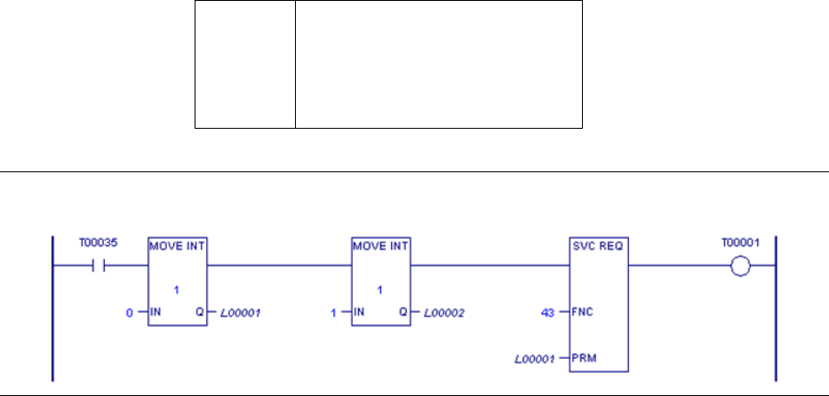
PACSystems™ RX3i Hot Standby CPU Redundancy User Manual Section 6
GFK-2308W May 2021
Operation 110
Command Block for SVC_REQ #43
The command block for SVC_REQ #43 has two words:
Address
0
Address+1
1 = Disable input and output copies
2 = Disable output copy only
Figure 40: Ladder Logic Example SVC_REQ 43
PACSystems™ RX3i Hot Standby CPU Redundancy User Manual Section 6
GFK-2308W May 2021
Operation 111
6.6.5 Validating the Backup Unit (SVC_REQ 43)
SVC_REQ 43 can be used to determine if the Backup unit is collecting inputs properly
(that is, validate the input scan). It can also be used to determine whether the Backup
unit is calculating outputs and internal variables properly (that is, validate the logic
solution).
Validating the Backup Unit’s Input Scan
To determine whether the Backup controller is collecting inputs properly, follow
these steps:
4. Activate SVC_REQ 43 on the Backup CPU, passing the values 0 and 1 to disable
the input and output data transfer copies.
5. Monitor the Backup unit's input references and input variables. The values
presented correspond to the inputs that the Backup is currently collecting.
6. Visually compare the Backup unit's input references and input variables with
those presented by the Active unit. Pay special attention to the references and
variables that are included in the input transfer.
7. When you are satisfied that the Backup unit is collecting inputs properly,
disable the rung that calls SVC_REQ 43.
Validating the Backup Unit’s Logic Solution
To determine whether the Backup unit is calculating outputs and internal variables
properly, follow these steps:
1. Activate SVC_REQ 43 on the Backup CPU, passing the values 0 and 2 to disable
the output data transfer copy.
2. Monitor the Backup unit's output references, output variables, and internal
variables. The values presented correspond to the values that the Backup is
currently calculating.
3. Visually compare the Backup unit's output references, output variables, and
internal variables with those presented by the Active unit. Pay special attention
to the references and variables that are included in the output transfer.
4. When you are satisfied that the Backup unit is calculating outputs and internal
variables properly, disable the rung that calls SVC_REQ 43.
6.7 Switching Control to the Backup Unit
Control switches from the Active unit to the Backup unit if:
1. The Active unit detects a fatal fault.
2. The Active unit is placed in Stop mode.
3. The Active unit fails or is powered off.
PACSystems™ RX3i Hot Standby CPU Redundancy User Manual Section 6
GFK-2308W May 2021
Operation 112
4. The toggle switch on an RMX module is activated, or the Role Switch command
is issued via the CPE400/CPL410 OLED redundancy menu.
5. A switch is commanded from the application program.
Note: These two types of requests (#4 and #5) are not honored if they occur within
10 seconds of the previous request, in which case they will be ignored.
6.7.1 PROFINET I/O Switchovers
For PROFINET I/O, whenever control switches from the Active unit to the Backup unit,
the new Active unit tells each redundantly controlled I/O device to make its
connection Active and start transferring inputs and outputs over that connection.
When this happens, the other unit’s connection to the I/O device becomes a Backup
connection. During this process, the redundantly controlled inputs and outputs
might hold last state for a short period of time.
The time that redundantly controlled PROFINET inputs and outputs hold their last
state during an I/O switchover typically will not exceed
(4 × IO cycle time) + (2 × CPU sweep time) + MSOT,
where MSOT is the MaxSwitchOverTime of the I/O device that contains these inputs
and outputs.
The MaxSwitchOverTime value is specified in the I/O device’s GSD file.
▪ For example, the MaxSwitchOverTime of the VersaMax PNS is 15ms.
6.7.2 Switching Times and Impact to Sweep Time
The amount of time needed to switch control from the Active unit to the Backup unit
depends on the reason for the switch.
There are two ways that the Backup unit detects that the Active unit has failed or lost
power.
1. Failure of all remaining redundancy links. This type of failure has negligible
impact on the controller sweep time.
2. Failure of the Active unit to rendezvous at a synchronization point within the
Fail Wait Time. An example of this type of failure is the CPU not responding
because the user logic is in an endless loop. If the redundancy links are still
operational, the increase to the sweep time will equal the Fail Wait Time.
For these two cases the switchover occurs immediately.
For all other cases, the switchover occurs just before the next input data transfer. The
maximum delay is 1 sweep. There may be an input and an output scan between
detection of the fatal fault and the switch.
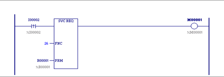
PACSystems™ RX3i Hot Standby CPU Redundancy User Manual Section 6
GFK-2308W May 2021
Operation 113
6.7.3 Commanding a Role Switch from the Application
Program (SVC_REQ 26)
The application program can use SVC_REQ 26 to command a role switch between the
redundant CPUs (Active to Backup and Backup to Active). As long as the units remain
synchronized, the switch occurs just before the input data transfer of the next sweep.
When SVC_REQ 26 receives power flow to its enable input, the controller is
requested to perform a role switch. Power flow from SVC_REQ 26 indicates that a
role switch will be attempted on the next sweep. Power flow does not indicate that a
role switch has occurred or that a role switch will definitely occur on the next sweep.
The role switch request is not valid if it occurs within 10 seconds of a previous
request. The 10-second limitation guarantees that only a single switch occurs if both
units make a request at approximately the same time. SVC_REQ 26 ignores the PARM
parameter; however, the programming software requires that an entry be made for
PARM. You can enter any appropriate reference here; it will not be used.
Example
In this example, a pushbutton switch on a control console is wired to input %I0002. In
the program logic, the reference for %I0002 is used as the input to the SVC_REQ 26
function block. When the button is pressed, logic power flows to SVC_REQ 26,
causing a role switch to be requested. The PRM reference is not used and can have
any value.
Figure 41: Ladder Logic for Role Switch (SVC_REQ 26)
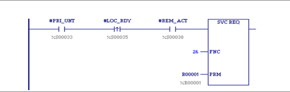
PACSystems™ RX3i Hot Standby CPU Redundancy User Manual Section 6
GFK-2308W May 2021
Operation 114
6.7.4 Implementing Preferred Master Using SVC_REQ 26
The PACSystems Hot Standby CPUs implement a floating master algorithm. This
means that when one unit is put into Run mode while the other unit is already in Run
mode, the transitioning unit always becomes the Backup unit.
If an application requires a preferred master algorithm where the Primary CPU always
becomes the Active unit when placed in Run mode, the logic can use the Role Switch
service request, SVC_REQ 26, as shown in the sample LD rung below. This logic must
be included in the Primary CPU and may also be included in the Secondary CPU.
Figure 42: Ladder Logic for Preferred Master (SCV_REQ 26)
6.8 STOP to RUN Mode Transition
A resynchronization will occur at all STOP to RUN mode transitions. The time to
perform this resynchronization may be larger than STOP to RUN transitions on non-
redundant CPUs. The STOP to RUN mode transition has two separate paths.
1. If the unit performing the transition is doing so alone or both units are
transitioning to Run at the same time, a normal STOP to RUN mode transition
is performed (clear non-retentive memory and initialize #FST_SCN and
#FST_EXE).
2. If the other unit is Active when this unit performs a STOP to RUN mode
transition, non-retentive references will be cleared followed by a
resynchronization with the Active unit.
6.8.1 Behavior with PROFINET I/O when No Healthy
Redundancy Links are Available
When no healthy redundancy links are available, a CPU will allow itself to be put into
RUN mode only if it has a connection to at least one redundant PROFINET I/O Device
and none of the devices to which it is connected report that the other PNC is
controlling its I/O.

PACSystems™ RX3i Hot Standby CPU Redundancy User Manual Section 6
GFK-2308W May 2021
Operation 115
Note: A special case exists when a standalone Primary CPU is set up to go to RUN
mode at power-up under circumstances where no Secondary PROFINET device
connection exists. The operation varies according to CPU type, as follows:
CPL410
CPE400
CPE330
Whenever there is no redundant link with the Secondary CPU, a
Primary CPU of this type waits a maximum of 20 seconds during
power-up for PROFINET redundant device connections to be
established. As soon as one PROFINET redundant device connection
is established (and no secondary PROFINET redundant device
connection exists) the Primary CPU can power up in RUN mode.
Otherwise, the Primary CPU powers up in STOP mode. If a
Redundant device PROFINET connection is established after the
timeout period expires, the standalone Primary CPU must be
manually switched from STOP to RUN mode.
CRU320
A Primary CPU waits only 3 seconds before attempting to go to
RUN, which is not enough time to establish connections to its
PROFINET devices. This means that a standalone Primary CRU320
always powers up into STOP mode. After the PROFINET connections
have been established, the standalone Primary CPU can be manually
switched to RUN mode. A standalone Secondary CRU320, however,
waits 30 seconds before attempting to go to RUN, which is
sufficient time to establish its PROFINET device connections. This
means that a standalone Secondary CPU can power-up into RUN
mode.
If any device indicates that the other PNC is controlling its I/O, the local CPU logs a No
Redundancy Links and Secondary CPU has control; Run mode not allowed or No
Redundancy Links and Primary CPU has control; Run mode not allowed fault and the
local CPU selects or remains in STOP mode.
If the local CPU is not connected to any redundant devices, the CPU logs a No
Redundancy Links and No redundant PROFINET Devices Connected; Run mode not
allowed fault and the local CPU selects or remains in STOP mode.
PACSystems™ RX3i Hot Standby CPU Redundancy User Manual Section 6
GFK-2308W May 2021
Operation 116
6.8.2 Validity of PROFINET I/O Immediately after a
Configuration Download
When you download a hardware configuration to a PACSystems controller, it can
take several seconds for that controller’s PNCs to come online and for each PNC to
bring its configured I/O devices online. The CPU does not prevent you from putting it
into RUN mode while it is in the process of bringing the PROFINET I/O online. Because
one can command a PACSystems CPU into RUN mode before all of its I/O devices are
ready, you should be aware of the following.
Inputs and Input Point Faults
When a redundantly-controlled PROFINET I/O device is not online with the Active
unit, the Active CPU sets that device’s inputs to the default values and sets the
corresponding input point faults to the faulted state. On a STOP to RUN transition,
these inputs and input point faults will remain in this state until that I/O device comes
online and starts transferring inputs to the PNC in the Active unit,
When a simplex PROFINET IO device is not online, the CPU for which that device is
configured will set that device’s inputs to the default values and set the
corresponding input point faults to the faulted state. On a STOP to RUN transition,
these inputs and input point faults will remain in this state until that I/O device comes
online and starts transferring inputs to corresponding PNC.
Therefore, if the control application needs to know whether a set of PROFINET inputs
is valid, it must refer to the input point faults.
Output Point Faults
When a simplex PROFINET I/O device is not online, the CPU for which that device is
configured for will set the output point faults for that device to the faulted state.
However, the Hot Standby CPUs do not support use of the output points faults
associated with redundantly-controlled PROFINET I/O Devices. Thus, the application
should not use the point faults that correspond to redundantly-controlled PROFINET
outputs.
6.9 RUN with Outputs Disabled Mode
RUN with Outputs Disabled mode causes all physical outputs to go to their default
state in that controller. Inputs are still scanned and logic is solved. A CPU in RUN with
Outputs Disabled mode may be the Active unit.
The following guidelines apply to using RUN/DISABLED mode with PACSystems Hot
Standby CPUs.
1. If a unit is in RUN/DISABLED mode, its #LOC_RDY %S reference and #REM_RDY %S
reference of the other unit are not set and the corresponding LEDs on the RMX
modules are OFF. This indicates that the unit (with #LOC_RDY reference off) is not
available to drive outputs.
2. If a unit is in RUN/ENABLED mode and the other unit is in RUN/DISABLED mode, the
unit in RUN/ENABLED mode does not use its synchronized fault action table.
PACSystems™ RX3i Hot Standby CPU Redundancy User Manual Section 6
GFK-2308W May 2021
Operation 117
Instead, it uses the user-configurable fault actions since there is no Backup
available to drive outputs.
3. Redundantly controlled PROFINET devices only enable their outputs if the Active
unit has its outputs enabled. This means that whenever the Active unit is in
RUN/DISABLED mode, the redundantly controlled PROFINET outputs are
commanded to their default states.
4. Redundantly controlled Genius devices and ENIUs will enable their outputs if either
unit (Active or Backup) has its outputs enabled. As long as these outputs are
included in the output transfer list, their values will be copied from the Active unit
to the Backup unit during the Output Data transfer. This means that the output
devices will be commanded to the output values that were calculated by the Active
unit. (There is one exception to this. It is described by item #5.)
Note: When a Genius output is connected to both Redundant CPUs, that
output should always be included in the output transfer list.
5. If the Outputs from Active Unit Only configuration parameter is enabled in an ENIU,
placing the Active controller in RUN/DISABLED mode will result in that ENIU’s
outputs being held in their last state.
Note: If the Backup unit is in RUN/DISABLED mode, the Backup unit
continues NOT to drive outputs upon failure of the Active unit and therefore is
not a complete Backup.
6.10 RUN to STOP Mode Transition
The behavior of a Hot Standby CPU Redundancy system when one of the two units
stops is dependent upon whether the two units were previously synchronized. If the
units were synchronized, the behavior also depends upon whether the stopped unit
was previously the Active unit.
▪ When the Backup unit from a pair of synchronized controllers goes to STOP mode,
the Active unit will continue to control the Redundant I/O.
▪ When the Active unit from a pair of synchronized controllers goes to STOP mode,
the Backup unit will become Active and take control of the Redundant I/O.
Additional information on the switchover process can be found in Section 6.7,
Switching Control to the Backup Unit.
Since most RUN to STOP transitions in a Hot Standby system occur as the result of a
fault condition, refer to Section 7:, Faults, for additional information.
6.10.1 Behavior with PROFINET I/O when no Healthy
Redundancy Links are Available
When a CPU that does not have any healthy redundancy links (for example, a
standalone CPU) goes from RUN to STOP, each of its PNCs will log a Loss of Device
fault for each redundant device that is present and configured. It will take
PACSystems™ RX3i Hot Standby CPU Redundancy User Manual Section 6
GFK-2308W May 2021
Operation 118
approximately 5 seconds for those PNCs to re-connect to at least one of those
devices (and log an Add’n of Device fault for it). During this period of time, the CPU
will not allow itself to be put back into RUN mode. If a second CPU (without healthy
redundancy links) is also present, it will exhibit the same behavior.
Once a CPU that does not have any healthy redundancy links goes from RUN to STOP,
that CPU will not see any faults from the redundant controlled IO Devices. Faults from
the devices will be ignored until either a) the CPU returns to RUN mode OR b) the
redundancy links are recovered. If a second CPU (without healthy redundancy links) is
present, it will exhibit the same behavior.
6.11 Error Checking and Correction
Error checking and correction (ECC) allows the CPU firmware to detect errors in
memory and correct some of them on the fly. This added layer of checking differs
from parity checking in that it can correct a single-bit error. If the ECC error is a single-
bit corrected error, the CPU generates a diagnostic fault and sets %SA0006 so that
you can know of a possible impending problem and take corrective action. If the ECC
error is a multi-bit error, which cannot be corrected, the CPU logs a fatal fault and
goes to Stop-Halt mode.
The Error Checking and Correction function of the memory controller is enabled on
the redundant CPU regardless of the Background Window Timer setting. This
provides parity like checking on the contents of every RAM location: the ECC bits are
set on every non-cached memory write and checked on every non-cached memory
read. If you are comfortable with the level of integrity checking that the ECC function
provides, you may choose to disable the additional background RAM tests entirely by
setting the Background Window Timer value to 0.
6.12 Timer and PID Functions
Timer and PID function blocks remain in lock-step between two synchronized units
provided:
1. Enabling logic for each function is identical on both units. This includes power
flow, how often the block is called, and so forth.
2. The block in which the function occurs has the same name in both units. Note
that _MAIN is always common.
3. Reference registers (3 for timers, 40 for PID), enabling references, and reset
references for each timer and PID function block are included in the data
transfer lists.
For example, if the following ladder logic appears in the _MAIN block on both units, %
M100, %R250, %R251, and %R252 must all be included in the output data transfer list
to keep this timer synchronized between the two units:

PACSystems™ RX3i Hot Standby CPU Redundancy User Manual Section 6
GFK-2308W May 2021
Operation 119
Figure 43: Ladder Logic for Synchronizing Timer
6.13 Timed Contacts
When both systems are synchronized, timed contacts (%S3, %S4, %S5, %S6) have
exactly the same value in both units. For example, whenever T_SEC is on in one unit,
it also is on in the other unit as long as both units are synchronized.
6.14 Multiple I/O Scan Sets
The Redundant CPU supports the configuration of multiple scan sets. However, it is
strongly recommended that the redundant I/O be configured in the default scan set
(Scan Set 1), which is scanned every sweep. The I/O scan set feature allows the
scanning of I/O points to be more closely scheduled with its use in user logic
programs.
If an I/O Scan set is not scanned every sweep, it is not guaranteed to be scanned in
the same sweep in the Primary and Secondary CPUs. For example, if the Primary and
Secondary CPUs each have a scan set that is scanned every other sweep (that is,
PERIOD=2), the Primary CPU might scan its scan set in one sweep and the Secondary
CPU scan its scan set in the next.
Use of non-default scan sets can cause variance in the time the units get to the
rendezvous points. This should be considered when determining the Fail Wait Time.
Redundantly controlled PROFINET inputs and outputs must be assigned to IO scan
sets that are scanned every sweep (such as Scan Set 1). This requirement is enforced
during CPU configuration.
6.15 Genius Bus Controller Switching
For PACSystems Hot Standby CPUs, Genius outputs are always enabled for both units
(unless explicitly disabled) so that bumpless switching is possible regardless of which
unit is currently the Active unit. Because of the way Genius Hot Standby operates, all
redundant Genius outputs must be included in the output transfer lists.
Genius Bus Controllers stop sending outputs to Genius devices when no output data
has been received from the CPU for a period equal to two times the configured
watchdog timeout.
If the Primary CPU becomes inoperative in an uncontrolled fashion (for example,
because of a power failure), the Genius Bus Controllers detect this within twice the
watchdog setting, and stop sending outputs to the Genius devices. After three
Genius I/O bus scans of not receiving data from the Genius Bus Controllers at Serial
Bus Address 31, the Genius devices use the output data supplied by the Genius Bus
PACSystems™ RX3i Hot Standby CPU Redundancy User Manual Section 6
GFK-2308W May 2021
Operation 120
Controller(s) at Serial Bus Address 30 (i.e. controlled by the Secondary CPU), if
available.
For example, if the system has a 200ms watchdog timeout and 5ms Genius bus scan
time, and the Primary CPU main rack loses power, any Genius Bus Controllers in
expansion racks will wait 400ms and then stop updating outputs on Genius devices.
After 3 scans (15ms in this example), the Genius devices will recognize that the data
supplied by SBA 31 is not being updated, and will begin to accept output data from
SBA 30 (i.e. from the Secondary CPU) and will begin to drive any output circuits based
on data from SBA 30. Note that any Genius Bus Controllers in the Primary CPU main
rack would stop driving outputs immediately since they would also lose power.
Genius devices on these buses would begin driving data from the Secondary CPU
within 15ms.
Note: For fastest switching, all Genius Bus Controllers in the Hot Standby CPU
Redundancy system should be installed in the main rack. This causes the Genius Bus
Controllers to lose power at the same time that the CPU loses power. This, in turn,
allows the Secondary CPU to gain full control of the I/O as soon as possible.
For single bus Genius networks, if outputs are not available on Serial Bus Address 30
or 31, the outputs on the devices revert to default or hold last state (as configured on
the individual Genius device).
For dual bus networks, if a Genius device detects that no output transmission is being
received from either Serial Bus Address 30 or 31 on a given bus, the BSM will switch to
the alternate bus. In the event output data is not available on either bus, then the
block’s outputs revert to default or hold last state (as configured on the individual
Genius device).
6.16 Redundant IP Addresses
Each unit contains at least one Ethernet interface that is assigned a direct IP address,
which is used to directly access the specific controller. A third, redundant, IP address
can be assigned to the pair of Ethernet interfaces in the Primary and Secondary
controller units. All data sent to the redundant IP address (including EGD produced to
the redundant IP address) is handled by the Active controller. When Active, the
Ethernet interface always initiates communications using the redundant IP address.
(EGD production is the only exception. EGD production can be configured to use
either the direct or redundant IP address as the source IP address.) When the
controller is in the Backup state, all communications are initiated through the direct
IP address.
Each Ethernet interface in the system can be set up as part of a pair that shares a
redundant IP address. Each unit can also include Ethernet interfaces that are not part
of a redundant IP pair.
6.16.1 Validation and Activation of Redundant IP Addresses
Immediately after configuration, neither Ethernet interface responds to the
redundant IP address. When notified by the CPU that the unit has become Active, the
Ethernet interface determines whether the redundant IP address is in use on the
network. If the address is not in use on the network, the Ethernet interface activates
the redundant IP address and sends out an address resolution protocol (ARP)
message to force all other Ethernet devices on the network to update their ARP
PACSystems™ RX3i Hot Standby CPU Redundancy User Manual Section 6
GFK-2308W May 2021
Operation 121
cache. This ARP message is sent so that communications to the redundant IP address
will be directed to the newly Active unit. At this point the Ethernet interface responds
to both the redundant IP address and its direct IP address. When commanded to
begin EGD production by the CPU, the Ethernet interface in the Active unit verifies
that it has successfully obtained the redundant IP address. EGD production does not
begin until the Ethernet interface obtains the redundant IP address.
If the redundant IP address is in use by another device on the Ethernet network, the
Ethernet interface periodically attempts to verify that the address is not in use. The
Ethernet interface attempts to verify the redundant IP address until it determines the
redundant IP address is no longer in use on the network or until the Ethernet interface
transitions to Backup due to either a notification from the CPU that the unit has
become the Backup unit or a failure that results in the Ethernet interface transitioning
to Backup.
6.16.2 Monitoring and Deactivation of Redundant IP Address
The Ethernet interface monitors the status of the CPU. If the Ethernet interface
determines that it can no longer communicate with the CPU, it deactivates the
redundant IP address. The Ethernet interface also deactivates the redundant IP
address when notified by CPU that the Active unit has transitioned to Backup.
When the Ethernet interface deactivates the redundant IP address, it transitions to
the Backup state. In the Backup state, the Ethernet interface no longer responds to
the redundant IP address, but forwards any packets received by the interface
destined for the redundant IP to the Ethernet interface in the Active controller. If the
Backup unit continues to receive packets destined for the redundant IP address, it
sends gratuitous ARP messages containing the redundant IP address and after a
number of time periods it logs an exception, which is recorded in the controller CPU
fault table as a LAN System Software Fault.

PACSystems™ RX3i Hot Standby CPU Redundancy User Manual Section 6
GFK-2308W May 2021
Operation 122
6.16.3 Operation of Redundant IP Address if both Redundancy
Links Fail
For systems that contain redundantly controlled PROFINET I/O, if both redundancy
links fail, the unit that was the synchronized Active unit goes to STOP mode. As a
result, the previously Active unit relinquishes the redundant IP address and the newly
Active unit is able to obtain it.
For systems that use redundantly controlled Genius or ENIU I/O, if both redundancy
links fail, both units can become non-synchronized Active units. In this case, both
units attempt to use the redundant IP address, but only one will succeed. If one of the
two units was already Active and responding to the redundant IP address, it
continues to do so; the unit that was Backup will not be able to activate the
redundant IP address.
CAUTION
When using the redundant IP feature with Genius or ENIUs, the application should
take steps to ensure that the CPU that owns the redundant IP address is the same CPU
that maintains control of the outputs. This becomes an issue when both CPUs are
operating as NSAUs (known as split control), since both units attempt to control the
process independently. Running both CPUs as NSAUs is not recommended and should
be corrected as soon as possible. Refer to Section0,

PACSystems™ RX3i Hot Standby CPU Redundancy User Manual Section 6
GFK-2308W May 2021
Operation 123
Online Repair Recommendations
Additional details on the operation of the Ethernet Interface can be found in
PACSystems RX3i and RSTi-EP TCP/IP Ethernet Communications User Manual, GFK-2224.
6.17 Ethernet Global Data in an HSB Redundancy
System
Note that two redundant units are not guaranteed to consume a given exchange on
the same controller sweep when using redundant IP. When using Produce in Backup
Mode, the Backup unit is not guaranteed to produce data on the direct IP at exactly
the same time the Active unit produces data on the redundant IP for a given
exchange.
6.17.1 Ethernet Global Data Production
By default, only the Active unit produces EGD exchanges. This reduces the amount of
traffic on the Ethernet network and simplifies the handling of the exchanges by the
consumer. In particular, the consumer is able to consume exchanges from the
redundant system in the same way it consumes exchanges from simplex (non-
redundant) systems.
Individual exchanges can be configured for Produce in Backup Mode. The Backup unit
produces these exchanges through the Ethernet module’s direct IP address.
If the controller is set to Stop-IO Disabled mode, outputs are disabled on the Active
unit, and neither unit produces EGD.
In an Ethernet Interface pair with Redundant IP enabled, a newly active Ethernet
interface arbitrates for the redundant IP address and delays EGD production
accordingly. If both redundant units become non-synchronized Active units (this can
occur if no redundancy links are functioning), for each redundant pair, the Ethernet
Interface that owns the redundant IP address will produce exchanges through the
Redundant IP address.
If Redundant IP is not enabled, the Ethernet Interfaces in both units produce
exchanges through their direct IP addresses.
The Producer ID as well as all production exchanges should be identical for both units.
This allows the consumer to continue consuming exchanges from the redundant
system when the Backup unit becomes Active.
Configuring Exchanges to be Produced in Backup Mode
In Machine Edition, to configure a production exchange to be produced in Backup
mode, go to the Project view, expand the Ethernet Global Data folder, select the
exchange and set its Produce in Backup Mode property to True.
To change the offset from the default value of 1000, select the Ethernet Global Data
folder and set the Secondary Produced Exchange Offset property to the desired
value.
PACSystems™ RX3i Hot Standby CPU Redundancy User Manual Section 6
GFK-2308W May 2021
Operation 124
For exchanges that are produced in Backup mode, an offset must be added to the
Exchange ID. This ensures that the Exchange ID is unique for those exchanges that
are produced simultaneously by the Active and Backup controllers.
For an HSB system using dual HWC, one set of EGD configuration data is used to
create EGD configuration files for both the Primary and Secondary controllers. When
Machine Edition creates the EGD exchange files for download to the Secondary
controller, it adds the Secondary offset to the Exchange ID for each exchange
configured to Produce in Backup.
For non-dual HWC systems, it is the user’s responsibility to ensure that the same
offset value is specified in both the Primary and Secondary target projects.
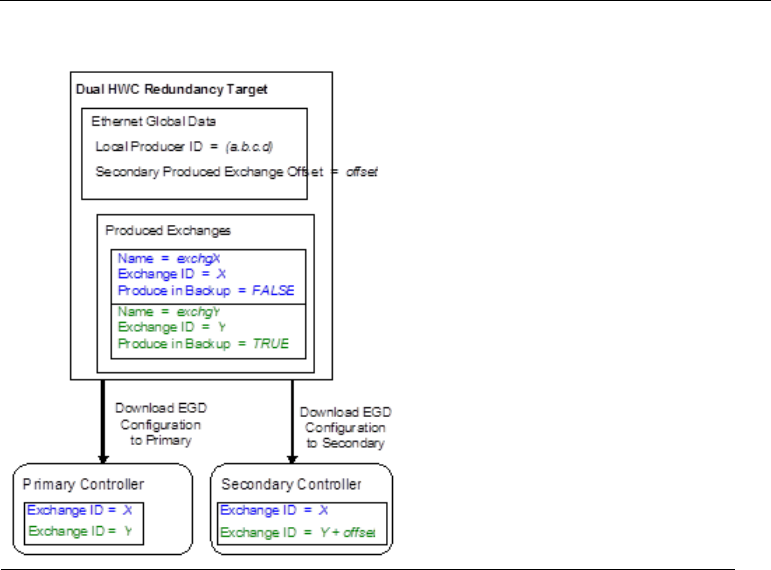
PACSystems™ RX3i Hot Standby CPU Redundancy User Manual Section 6
GFK-2308W May 2021
Operation 125
Figure 44: Exchange ID Offset in Dual HWC HSB System
6.17.2 Ethernet Global Data Consumption
Both the Active and Backup units consume EGD exchanges in RUN mode, regardless
of whether or not the units are synchronized.
It is recommended that all consumption exchanges be configured identically for both
units. In addition, these exchanges must be configured as multicast or directed to the
Redundant IP address.
The consumption of multicast exchanges occurs independently on the two units. The
Ethernet modules obtain a copy of multicast exchanges at the same time, but
reading of that exchange in the two CPUs may be phased by one sweep. This can
result in the two units seeing different values for the same exchange in a given
sweep. Only the Active unit consumes exchanges directed to the Redundant IP
address.
If data from the exchanges must be seen identically on the two units, the reference
data for the exchanges can be transferred from the Active unit to the Backup unit
during the input data transfer. That transfer occurs shortly after the EGD
consumption portion of the CPU sweep. Exchange variables transferred must be
placed into %I or %AI memory to participate in the input data transfer.

PACSystems™ RX3i Hot Standby CPU Redundancy User Manual Section 7
GFK-2308W May 2021
Faults 126
Section 7: Faults
This chapter describes how faults are handled in a Hot Standby CPU Redundancy
system.
▪ Fault Response
▪ Fault Actions
▪ Controller Fault Table Messages for Redundancy
▪ Redundancy Link Failures
▪ Online Repair and System Upgrade
7.1 Fault Response
CAUTION
When using the redundant IP feature with Genius or ENIUs, the application should
take steps to ensure that the CPU that owns the redundant IP address is the same CPU
that maintains control of the outputs. This becomes an issue when both CPUs are
operating as NSAUs (known as split control), since both units attempt to control the
process independently. Running both CPUs as NSAUs is not recommended and should
be corrected as soon as possible. Refer to Section0,

PACSystems™ RX3i Hot Standby CPU Redundancy User Manual Section 7
GFK-2308W May 2021
Faults 127
Online Repair Recommendations
The Hot Standby CPU Redundancy system detects and reports failures of all critical
components so that appropriate control actions can be taken. All components that
acquire or distribute I/O data or that are involved in execution of the control logic
solution are considered critical components.
A fatal fault in the Active unit causes a switch of control to the Backup unit. A
diagnostic fault allows the currently Active system to continue operating as the
Active system.
Faults within the unit may be such that:
3. The CPU has a controlled shutdown,
4. The CPU has an uncontrolled shutdown, or
5. The CPU continues to operate.
If the CPU detects an internal fault and has a controlled shutdown, it logs a fault, goes
to Stop/Fault mode, and notifies the other CPU. If the fault was detected on the
Active unit, the switchover does not normally occur until the next sweep. The
exception is when the Active unit detects a fatal fault during the input scan. In that
case, the two units switch roles just before performing the input data transfer.
If the CPU has an uncontrolled shutdown, the CPU logs a fault if it can and proceeds
as described above. When the Backup CPU detects that the Active CPU has failed
(either by receiving notification, by detecting that both redundancy links have failed,
or by detecting failure of the Active CPU to rendezvous at the next synchronization
point within the Fail Wait Time) it becomes an unsynchronized Active unit.
For cases where both redundancy links have failed, including the Fail Wait Timeout
case, refer to Section 7.4.3, When the Last Redundancy Link Fails.
7.1.1 Faults for PROFINET I/O
When a redundantly-controlled PROFINET IO Device reports a fault, that fault only
appears in the unit that was Active when the fault was reported. These faults do not
appear in the Backup unit. Examples of these faults are: Loss of I/O Module, Addition
of I/O Module, Channel Diagnosis Appears (for example, Power supply fault), and
Channel Diagnosis Disappears.
However, whenever a controller loses communication with an entire PROFINET IO
Device, a Loss of Device fault will appear in that unit regardless of whether that unit is
Active or Backup. The same is true for Addition of Device faults. Also, whenever a
controller establishes a connection to an IO-Device, faults for missing and
mismatched I/O modules will always appear in that controller regardless of whether it
is Active or Backup.
When the CPU or rack has failed, faults detected at the PROFINET I/O controller (PNC)
are logged locally at the PNC module, but cannot be delivered to the CPU’s I/O Fault
table.
7.2 Fault Actions
PACSystems™ RX3i Hot Standby CPU Redundancy User Manual Section 7
GFK-2308W May 2021
Faults 128
Fault actions in the Hot Standby CPU Redundancy System are handled differently
than fault actions in a simplex (non-redundant) system. When the units are
synchronized, the types of faults that are considered to be FATAL (i.e., cause the CPU
to stop) are not configurable. The following types of faults are considered FATAL
when the units are synchronized:
▪ Any failure that causes loss of control of I/O
▪ Any failure that degrades the performance
Note: In a Hot Standby CPU redundancy system, a Fatal fault from an I/O Controller
causes a synchronized unit to transition to STOP/FAULT mode. All Diagnostic faults
allow the CPU to remain in Run mode.
PACSystems™ RX3i Hot Standby CPU Redundancy User Manual Section 7
GFK-2308W May 2021
Faults 129
7.2.1 Configuration of Fault Actions
You can configure whether certain faults are considered fatal when the CPUs are not
synchronized.
The following should be considered when configuring the fault actions for a
redundant CPU. For a given fault that is fatal for the synchronized case, if you set the
non-synchronized fault action to be diagnostic, there is a chance that a less healthy
unit could remain the Active unit even after a healthier Backup unit is placed in Run
mode. For example, if you were to configure Loss of or Missing Rack failures as
diagnostic, the following sequence of events could occur:
1. If an expansion rack fails when the units are synchronized, the unit with the
rack failure will transition to STOP/FAULT mode and the other unit will become
a non-synchronized Active unit.
2. If an expansion rack fails in the non-synchronized Active unit, a diagnostic fault
will be logged but the unit will stay in RUN mode and continue to control the
process.
3. If the first unit is repaired and then transitions to Run, the second unit with the
failed expansion rack will stay in RUN mode and will remain in control of the
process.
To prevent this situation, you could include logic to shut down the less healthy unit or
request a role switch.
Also, a unit with the fault actions set to diagnostic can be placed in RUN mode and
become the Active unit even though it could have a diagnostic fault, which would be
logged as fatal in a synchronized system.
For example, if an expansion rack fails while in STOP mode or while transitioning to
RUN mode, a diagnostic fault is logged. However, the unit will still transition to RUN.
In addition, if you have programmed a Preferred Master algorithm, this unit will
become the Active unit. To prevent this situation, you could include logic to shut
down the less healthy unit or modify the role switch logic.

PACSystems™ RX3i Hot Standby CPU Redundancy User Manual Section 7
GFK-2308W May 2021
Faults 130
7.2.2 Configurable Fault Groups
The following table shows the configurable fault groups and their fault actions. There
are three possible fault actions:
Fatal
Faults always stop the controller.
Diagnostic
Faults never stop the controller.
Conditionally Fatal
Faults stop the controller if and only if the I/O Controller
indicates that the fault is fatal.
Group
Name
Table
Type
Non-Synchronized Fault
Action
Synchronized Fault
Action (fixed)
Default
Configurable
1
Loss of or Missing Rack
Controller
Diagnostic
Yes
Fatal
2
Loss of or Missing I/O
Controller
I/O
Diagnostic
Yes
12
Fatal
3
Loss of or Missing I/O
Module
I/O
Diagnostic
Yes
Diagnostic
4
Loss of or Missing Option
Module
Controller
Diagnostic
Yes
Diagnostic
9
IOC or I/O Bus Fault
I/O
Diagnostic
Yes
Conditionally Fatal
13
11
System Configuration
Mismatch
Both
Fatal
Yes
Diagnostic
12
System Bus Error
Controller
Fatal
Yes
Fatal
15
IOC Software Failure
I/O
Diagnostic
Uses LOSS_IOC
setting
Conditionally Fatal
13
24
CPU Over Temperature
Controller
Diagnostic
Yes
Fatal
38
Recoverable Local
Memory Error
Controller
Diagnostic
Yes
Diagnostic
12
Even if the non-synchronized fault action for the Loss of IOC fault group is configured as Fatal, the Controller will not go to
STOP/FAULT mode unless both Genius Bus Controllers of a dual bus pair fail.
13
Conditionally Fatal: When an I/O Controller logs a fault in one of these fault groups, it notifies the Controller whether it can continue
to operate or not by placing Diagnostic or Fatal in the fault’s Fault Action field. For the cases where the table above indicates
Conditionally Fatal, the Controller applies the fault action selected by the I/O Controller.

PACSystems™ RX3i Hot Standby CPU Redundancy User Manual Section 7
GFK-2308W May 2021
Faults 131
7.2.3 Non-Configurable Fault Groups
The table below shows the non-configurable fault groups and their fault actions.
There are two possible fault actions: Fatal and Diagnostic.
▪ Fatal faults always stop the controller;
▪ Diagnostic faults never stop the controller.
Group
Name
Table Type
Fault Action
5
Addition of or Extra Rack
Controller
Diagnostic
6
Addition of, Reset of, or Extra IOC
I/O
Diagnostic
7
Addition of, Reset of, or Extra I/O Module
I/O
Diagnostic
8
Addition of, Reset of, or Extra Option Module
Controller
Diagnostic
10
I/O Module Fault
I/O
Diagnostic
12
System Bus Error
Controller
Fatal
13
CPU Hardware Failure
Controller
Fatal
14
Module Non-Fatal Hardware Error
Controller
Diagnostic
16
Option Module Software Failure
Controller
Diagnostic
17
Program Block Checksum Mismatch
Controller
Fatal
18
Low Battery
Controller
Diagnostic
19
Constant Sweep Time Exceeded
Controller
Diagnostic
20
Controller Fault Table Full
Controller
Diagnostic
21
I/O Fault Table Full
Controller
Diagnostic
22
User Application Fault
Controller
Diagnostic
129
No User Program Present at power-up
Controller
Diagnostic
130
Corrupted User Memory
Controller
Fatal
131
Window Completion Failure
Controller
Diagnostic
132
Password Access Failure
Controller
Diagnostic
134
NULL System Configuration for RUN Mode
Controller
Diagnostic
135
CPU Software Failure
Controller
Fatal
137
Controller Sequence Store Failure: Communication failure during a store operation
by the programmer. This fault results when the start-of-store sequence was
received but not an end-of-store sequence.
Controller
Fatal
138
Redundancy Informational Message
Controller
Informational

PACSystems™ RX3i Hot Standby CPU Redundancy User Manual Section 7
GFK-2308W May 2021
Faults 132
7.2.4 Fatal Faults on Both Units in the Same Sweep
It is very unlikely that a fatal fault would occur on both units in the same sweep. If that
should happen, however, the first CPU to detect a fatal fault will use the synchronized
fault action table. The other CPU will use the non-synchronized fault action table. This
allows one of the units to stay in Run mode when the synchronized fault action is
Fatal and the non-synchronized fault action is diagnostic.
7.3 Controller Fault Table Messages for
Redundancy
The following table lists messages, descriptions, and corrective actions for error
codes associated with the redundancy fault group. These error codes can be viewed
in the Fault Tables provided by Machine Edition. The entire fault data (including these
error codes) can also be accessed using SVC_REQ 15 and 20.
7.3.1 Redundancy Fault Group (138)
Error
Code
Message
Fault Description
Corrective Action
1
Primary CPU is Active
and Secondary CPU is
Backup.
The Primary and Secondary CPUs have
switched roles, the Secondary
transitioned to Run after the Primary,
or both units transitioned to Run at
the same time.
None required.
2
Secondary CPU is Active
and Primary CPU is
Backup.
The Secondary and Primary CPUs have
switched roles, or the Primary
transitioned to Run after the
Secondary.
None required.
3
Primary CPU is Active; no
Backup unit available.
The Primary CPU has transitioned to
Run mode or Secondary CPU was put
into Stop mode. The Primary CPU is
running without a Backup.
To have a synchronized
system, the Secondary CPU
must be placed in RUN mode
with a compatible
configuration.
4
Secondary CPU is Active;
no Backup unit available
The Secondary CPU has transitioned
to RUN mode or Primary CPU was put
into Stop mode. The Secondary CPU is
running without a Backup.
To have a synchronized
system, the Primary CPU
must be placed in RUN mode
with a compatible
configuration.

PACSystems™ RX3i Hot Standby CPU Redundancy User Manual Section 7
GFK-2308W May 2021
Faults 133
Error
Code
Message
Fault Description
Corrective Action
5
Primary CPU has failed;
Secondary CPU is Active
w/o Backup.
The Primary CPU has recorded a fatal
fault or the Secondary has lost
communications with the Primary.
The Secondary CPU is running without
a Backup.
If Primary CPU has also
logged the fault Secondary
CPU Has Failed: Primary CPU
is Active w/o Backup,
communications are broken
between the two units and
must be repaired. If a fatal
fault has been logged in the
Primary CPU, the indicated
fault must be repaired. Power
may have to be cycled on one
of the units in order to re-
establish communications
and return to a synchronized
system.
6
Secondary CPU has
failed; Primary CPU is
Active w/o Backup.
The Secondary CPU has recorded a
fatal fault, or the Primary CPU has lost
communications with the Secondary.
The Primary CPU is running without a
Backup.
If Secondary CPU has also
logged the fault Primary CPU
Has Failed: Secondary CPU is
Active w/o Backup,
communications have been
broken between the two
units and must be repaired. If
a fatal fault has been logged
in the Secondary CPU, the
indicated fault must be
repaired. Power may have to
be cycled on one of the units
in order to re-establish
communications and return
to a synchronized system.
8
Unable to Switch
Redundancy Roles
An attempt to switch redundancy
roles was made when it was not
possible to perform the switch.
None required.
9
Primary and Secondary
CPUs are incompatible
This unit could not be placed into RUN
mode because the configurations
were not compatible.
Correct the configurations so
that the CPUs have
compatible transfer lists and
the same point faults
enabled setting. In addition,
if one CPU has redundantly
controlled PROFINET I/O
configured, the other CPU
must also have redundantly
controlled PROFINET I/O
configured.

PACSystems™ RX3i Hot Standby CPU Redundancy User Manual Section 7
GFK-2308W May 2021
Faults 134
Error
Code
Message
Fault Description
Corrective Action
10
CPU to CPU
communications
terminated
Synchronization protocol has been
violated.
Contact Technical Support.
If the fault is accompanied by
a Loss of Module fault, see
corrective action for ‘Loss of
Module’ fault.
The link can be restored to
service by power cycling
either unit or storing
configuration to either unit.
11
Redundant Link has
timed out
The CPU has timed out while waiting
on communications from the other
unit.
Contact Technical Support.
The link can be restored to
service by power cycling
either unit or storing
configuration to either unit.
12
Units Are Not Fully
Synchronized
Due to actions taken by the user, the
two units in a CPU redundant system
are not fully synchronized. This means
the Backup unit is not executing with
the same inputs and/or outputs as the
Active unit while the units are
synchronized due to data transfers
being disabled.
Disable the logic that
executes SVC_ REQ 43.
14
Redundant link
communication failure
Communications with the other CPU
over this link have failed.
If the other unit failed or lost
power, cycle power to it.
Verify one CPU is configured
for Primary and the other for
Secondary. Check the cable
connections between the
two RMX modules.
If the fault is accompanied by
a Loss of Module fault, see
corrective action for Loss of
Module fault.
Otherwise, contact Technical
Support.
15
Fail Wait Time exceeded
The other CPU failed to rendezvous at
a synchronization point within the Fail
Wait Time.
Increase the configured Fail
Wait Time.
17
Could not synchronize
with the remote.
The remote unit is unable to
synchronize with the local unit
because it is performing an RMS.
Attempt to synchronize after
the remote unit completes
its RMS.
18
No Redundancy Links;
Secondary took control
The Primary CPU stopped because the
last redundancy link failed and the
Secondary CPU took control of the
I/O.
Repair the redundancy links.
Refer to Section 7.4,
Redundancy Link Failures.

PACSystems™ RX3i Hot Standby CPU Redundancy User Manual Section 7
GFK-2308W May 2021
Faults 135
Error
Code
Message
Fault Description
Corrective Action
19
No Redundancy Links;
Primary took control
The Secondary CPU stopped because
the last redundancy link failed and the
Primary CPU took control of the I/O.
Repair the redundancy links.
Refer to Section 7.4,
Redundancy Link Failures.
23
RDN_Link_Comm_
Restored
“Redundancy link communications
restored”. This fault is logged when
the system detects that at least one of
the Redundancy Ethernet links has
been reconnected.
This fault does not indicate
that the system is
synchronized. A manual Stop
to Run transition is required
for synchronization.
24
RDN_Enet_Link_Lost
“Redundancy Ethernet link lost”. This
fault is logged when the system
detects that one of the Redundancy
Ethernet links is lost. A disconnected
cable usually causes this.
Examine LAN3 cabling and
connections.
25
RDN_Enet_Link_Restore
d
“Redundancy Ethernet link restored”.
This fault is logged when the system
detects that one of the Redundancy
Ethernet links that were previously
lost is restored.
No further action required

PACSystems™ RX3i Hot Standby CPU Redundancy User Manual Section 7
GFK-2308W May 2021
Faults 136
7.3.2 Other Fault Groups
The following table lists messages, descriptions, and corrective actions for error
codes associated with redundancy in other fault groups.
Group
Error
Code
Message
Fault Description
Fault Description
Corrective Action
Loss of IOC (2)
None
Loss of IOC
The CPU generates this
error when it cannot
communicate with an
I/O Controller and an
entry for the IOC exists
in the configuration file.
Install the missing
module or correct the
configuration.
Otherwise, replace
the module and
contact Technical
Support.
Loss of Option
Module (4)
Various
Loss of or missing
option module
or
Redundant link
hard failure
occurred
The module is missing
or the CPU has
determined that the
module has failed.
Install the missing
module or correct the
configuration.
Otherwise, replace
the module and
contact Technical
Support.
1
Invalid module
configuration
CPU or PNC versions
might not support
redundant.ly controlled
PROFINET I/O.
Update to latest CPU
and PNC firmware
version.
2
Unsupported
module
configuration
detected
5
Error processing
backplane
interrupt
CCPU does not support
I/O module interrupts.
Remove I/O interrupts
from configuration.
10
Multiple Media
Redundancy
Managers MRMs)
detected
Multiple MRMs have
been detected on the
ring network. There
must be exactly one
manager.
Identify and remove
the extra MRM.
11
Multiple MRMs
resolved
Multiple MRMs are no
longer present on the
ring network.
None required.
12
Redundant
Ethernet network
ring broken (open)
The MRM has detected
that the network ring is
broken. Possible causes:
pulled or broken
network cable, device in
the ring failed, etc.
Locate and repair the
network break.
13
Redundant
Ethernet network
ring okay (closed)
The MRM has detected
that the network ring is
closed.
None required.

PACSystems™ RX3i Hot Standby CPU Redundancy User Manual Section 7
GFK-2308W May 2021
Faults 137
Group
Error
Code
Message
Fault Description
Fault Description
Corrective Action
Various
Internal runtime
error
Software error at PNC
module
Contact Technical
Support.
CPU System
Software (135)
148
Units contain
mismatched
firmware; update
recommended.
The redundant CPUs
have different firmware
revision levels. Having
different revisions of
firmware in the CPUs is
intended for short-term
synchronization only.
Upgrade the CPUs so
that they have the
same revision of
firmware according to
the firmware upgrade
procedure.
Configuration
Mismatch (11)
75
ECC jumper should
be enabled, but is
disabled
When redundancy
firmware is installed in
the CPU module, the
ECC jumper must be in
the enabled position.
Set the ECC jumper to
the enabled position
(jumper on both pins).
See the instructions
provided with the
firmware upgrade kit.
Recoverable
Local Memory
Error (26)
1
Recoverable local
memory error
A single-bit error was
encountered and
corrected. %SA00006 is
set.
The CPU may need to
be replaced. Contact
Technical Support.
CPU Hardware
(13)
169
Fatal local memory
error
Multiple bit ECC error.
Replace the CPU and
contact Technical
Support.
7.4 Redundancy Link Failures
There are distinct differences between losing an RMX redundancy link and faulting an
RMX module.
7.4.1 Redundancy Memory Xchange Module Hardware
Failure
Failures such as backplane errors are considered hardware failures of the RMX
module. The following actions are taken when such an error is detected:
▪ Either a Loss of or Missing Option Module or a Redundant Link Hard Failure Occurred fault is logged
in the Controller Fault Table
▪ A Redundant Link Communications Failure fault is logged in both units.
▪ All LEDs on the RMX module are turned OFF.
▪ The fault locating references that correspond to the module are set (i.e. the SLOT_ 00XX fault
contact is set, where XX is the slot number for the RMX module).
▪ The corresponding redundancy link is no longer used. If the other link is still operating, that link is
used for all further data transfer, and the units can remain in synchronization. If the other
redundancy link is not available, refer to Section 7.4.3, When the Last Redundancy Link Fails.
PACSystems™ RX3i Hot Standby CPU Redundancy User Manual Section 7
GFK-2308W May 2021
Faults 138
Power must by cycled on the rack to restore a faulted RMX module to service.
7.4.2 Redundancy Link Communications Failures
The following errors are reported as failures of the redundancy link:
▪ The other unit has lost power or failed such that it can no longer communicate.
▪ One or both cables between the two RMX modules have failed or are disconnected.
▪ A network error was detected on the fiber-optic link that connects the two RMX modules. (This
includes data checks on mismatches, protocol errors, and rogue packets.)
▪ Failure of the other CPU to rendezvous at the next synchronization point within the Fail Wait Time.
The following actions are taken when a redundancy link communications failure
occurs:
1. Either a Redundant Link Communications Failure or Fail Wait Time Exceeded fault
is logged in the Controller Fault Table of both units.
2. The LINK OK LEDs on both RMX modules are turned off.
3. The fault locating references that correspond to the module are set (i.e. the SLOT_
00XX fault contact is set, where XX is the slot number for the RMX module).
4. The corresponding redundancy link is no longer used. If the other link is still
operating, that link is used for all further data transfer, and the units can remain in
synchronization. If the other redundancy link is not available or a Fail Wait Timeout
occurred, refer to Section 7.4.3, When the Last Redundancy Link Fails.
If the RMX modules’ OK LEDs are still ON, the link can be restored to service by power
cycling either unit or storing a hardware configuration to either unit. If either OK LED
is OFF, power must be cycled on the rack to restore that RMX module to service.
7.4.3 When the Last Redundancy Link Fails
This section describes how the system will behave when the last healthy redundancy
link between a pair of synchronized controllers fails. This includes the case where one
CPU does not rendezvous at a synchronization point within the Fail Wait Time.
PROFINET I/O Systems
When the last redundancy link fails, the Backup unit assumes that the Active unit has
failed and takes control of the redundant I/O. As long as at least one redundantly
controlled PROFINET I/O Device is online with both units, the Active unit will detect
that it has lost control of the redundant I/O: it logs a No Redundancy Links; Secondary
[or Primary] took control fault and goes to Stop mode. The Backup unit becomes an
NSAU and takes control of the redundantly controlled I/O devices.
However, if no redundantly controlled I/O Devices are online with both units when
the last redundancy link fails, both units remain in Run mode and proceed as NSAUs.
Each unit controls any simplex or redundantly controlled I/O Devices to which it was
exclusively connected.
PACSystems™ RX3i Hot Standby CPU Redundancy User Manual Section 7
GFK-2308W May 2021
Faults 139
When one unit is powered off, or when its CPU or rack completely fails, the other unit
becomes an NSAU and takes control of the redundantly controlled IO Devices.
When both units are powered off at the same time, or when the only functioning unit
is powered off, the PROFINET I/O Devices have no connections to any controller. The
PROFINET I/O Devices set their outputs to default states.
Genius and ENIU I/O Systems
When the last redundancy link fails, both units log faults and proceed as non-
synchronized Active units. In this case both units attempt to control the process
independently. The redundant Genius devices that are connected to both units will
prefer the output values sent by the Primary CPU.
7.4.4 CPE400/CPL410 Redundant Link Recovery
A Redundant CPE400/CPL410 has the ability to recover single and double Ethernet
link losses.
Single Link Loss
If one of the 2 Ethernet cables is disconnected from the Redundant Pair, the
Redundancy link communications will continue on the remaining link. The user can
then reconnect the lost cable and communications will be restored on that cable
almost immediately. Ethernet Link Lost/Restored faults will be logged in the
controller fault table.
Double Link Loss
If both of the Ethernet cables are disconnected from the Redundant Pair, Redundancy
Communication will cease and synchronization will be lost. A Redundancy Link
Communication failure fault, and a fault for each Ethernet link lost will be logged on
the controller fault table. If the user reconnects 1 of the 2 Ethernet cables, the system
will restore the Redundancy Communications after 10 seconds and log a Redundancy
Communications Restored fault, in addition to an Ethernet Link Restored fault for
each connection made.
Note: The System will not automatically restore the redundancy state
(Active/Backup), just the communications. The user will have to do a manual
STOP/RUN transition to get the units synchronized again.
7.5 Online Repair and System Upgrade
With a Hot Standby CPU Redundancy system, most system component failures can
be repaired by replacing the failed component while the system is online. You could
choose to replace components for other reasons, such as upgrading to a new model
of a module. CPUs in both units must have the same model types and firmware
version.
PACSystems™ RX3i Hot Standby CPU Redundancy User Manual Section 7
GFK-2308W May 2021
Faults 140
7.5.1 Online Repair Recommendations
Note: If the LOCAL ACTIVE LEDs are ON and the REMOTE ACTIVE LEDs are OFF on
both units, the system is operating under split control, that is, with both units
operating as NSAUs. Do not use this procedure if this condition exists, since neither
unit has the Backup role. Additionally, in a system that uses ENIU I/O, there is no
guarantee that all ENIUs are taking outputs from the same controller. Refer to
Section 7.5.6, Repair of a Non-Synchronized Active Unit (NSAU) Split Control System.
To replace a component online, it is strongly recommended that you follow this
procedure:
1. Make sure the unit to be repaired is the Backup unit. (The LOCAL ACTIVE LED
should be OFF and the REMOTE ACTIVE LED should be ON. You can also
confirm this by viewing the Redundancy tab of the programmer’s online status
dialog box.) If the unit to be repaired is already in Stop mode, skip this step. If
the unit to be repaired is Active, activate the Role Switch on the RMX module.
2. Power-off the unit to be repaired.
3. Replace the defective component.
4. On the CPU of the repaired unit, place the Run/Stop switch in the Stop position.
5. Power on the repaired unit.
6. After several seconds, verify that the LINK OK LEDs are ON for all RMX modules
in both units. If the LINK OK LEDs are not on, refer to the Controller Fault Table.
7. If the repaired CPU is in Stop/Fault mode, verify that there are no unexpected
faults and then clear the Fault Tables.
8. Place the repaired unit into RUN mode by putting the Run/Stop switch in the
Run position.
7.5.2 Hot Swapping of Modules (RX3i Systems Only)
RX3i redundancy systems support hot swapping of modules to the same extent
allowed in simplex systems. Modules that support hot swapping can be removed and
replaced in the RX3i main rack and in ENIU remote racks while the rack is powered up.
For a list of modules that support hot swapping, refer to the PACSystems RX3i System
Manual, GFK-2314.
Hot Swapping RMX 128 Modules
The RX3i RMX128/RMX228 module supports hot insertion and removal. However,
the redundancy communication link associated with a hot swapped RMX module will
not be restored automatically. The LINK OK indicator on both RMX modules in the
link will be OFF.
To restore the link while the system is in operation, first determine which unit is the
Backup unit, and if possible, cycle power or store hardware configuration to that unit.
PACSystems™ RX3i Hot Standby CPU Redundancy User Manual Section 7
GFK-2308W May 2021
Faults 141
If either RMX module’s OK indicator is OFF, power must be cycled on the rack to
restore the RMX module to service.
7.5.3 Hot Swapping Controllers (CRU320 to CPE330)
In a redundancy system, the CRU320 controller (v8.95) in an inactive system can be
removed and replaced by a CPE330 (v9.75) while the active system is hot.
The following procedure outline best practices for the (process) hotswap:
1. Identify the non-active unit through the LEDs on the front panel of the RMX
module.
2. Place the non-active CPU in Stop Mode.
3. Power down the system that is in Stop mode.
4. On the replacement CPE330, put the RUN/STOP switch into Stop Mode and
place the unit into the rack.
5. Hold down the RDSD UPLD button and turn power on to the CPE330.
Continue to press the RDSD UPLD button until the CPE330 powers up and
displays either the CPU or CRU pattern on the LEDs. (For pattern
information, see Section 2.2.3.6, Indicators CPE330 in GFK-2222.)
6. To toggle the compatibility setting, press the RDSD DNLD button and select
the CRU320 compatibility mode. Note: The compatibility indicator will
toggle between the CPU320 compatibility and CRU320 compatibility
patterns each time the RDSD DNLD button is pressed.
7. Press the RDSD UPLD button to save the setting and allow the CPE330 to
continue its normal startup procedures with the new setting. The setting is
maintained over a power cycle and firmware upgrade.
8. [Optional] If LAN 1 has been previously configured on the CPE330, you can
connect a web browser to the CPU and verify that the CPU is listed as being
in "CRU320 Compatibility mode.”
9. Connect PME, right-click the (non-active) target and select “Download.”
10. Verify that each of the 4 LEDs (OK, CONFIG, SIG DETECT and OWN DATA), are
all turned ON to signify the module is operating properly.
11. Go to Run Mode.
12. Use the switch on the front panel of the RMX to perform a Role Switch so
the newly replaced CPE330 becomes the active system according to the
LEDs on the front panel of the RMX.
7.5.4 System CPU Upgrade
If you are upgrading your redundancy system with new CPU models, you will need to
replace the CPUs in both units. To replace the CPUs in your redundancy system,
follow the steps in Section 7.5.1, Online Repair Recommendations. When you have
replaced the CPU in the Backup unit and returned it to RUN mode, activate the Role
Switch on the RMX module and repeat steps 1–8 for the other unit.

PACSystems™ RX3i Hot Standby CPU Redundancy User Manual Section 7
GFK-2308W May 2021
Faults 142
CAUTION
During normal operation, the Primary and Secondary CPUs in an HSB redundancy
system must have the same CPU model type. Extended operation with dissimilar CPU
types is not allowed. Continued use of dissimilar CPU types can result in timing issues
during synchronization
The Primary and Secondary CPUs with dissimilar CPU model types can be
synchronized for a limited time, for the purpose of system upgrade only. Fail wait
times for the higher performance CPU in a dissimilar redundant pair might need to be
increased to allow synchronization. It does not matter whether the newer model is in
the Primary or Secondary CPU.
7.5.5 Online Repair of the Genius Bus
Single Bus Networks
The Genius bus of a single bus network can be repaired without disturbing power to
either unit. However, repairing the bus without taking the entire Hot Standby CPU
Redundancy system offline is not recommended because all devices on that bus will
be disconnected from the controllers while the bus is being repaired.
Dual Bus Networks
The Genius bus of a dual bus network can be repaired without disturbing power to
either unit. It is recommended that you disconnect the failed bus from the GBCs
before you attempt to repair it.
PACSystems™ RX3i Hot Standby CPU Redundancy User Manual Section 7
GFK-2308W May 2021
Faults 143
7.5.6 Repair of a Non-Synchronized Active Unit (NSAU) Split
Control System
When Redundant CPUs lose all redundancy links and become NSAUs, there is a
possibility of split control or of a failed rack controlling outputs.
In a split control situation, some of the Remote I/O devices are taking outputs from
one Redundant CPU and the other Remote I/O devices are taking outputs from the
other CPU. In this situation turning off one of the controllers could result in defaulting
the outputs of some of the Remote I/O devices.
A situation where a failed rack controls the outputs occurs when the failed RMX
module is contained in the same rack as the CPU that is currently controlling Remote
Device outputs.
The procedures given in this section discusses ways to reduce the chance of
defaulting outputs on some of the Remote I/O devices controlled by the Redundant
CPU pair. Although these procedures might prevent defaulting outputs, they might
also involve a short disruption in the outputs as the Remote I/O devices switch to
taking outputs from the other CPU. It is incumbent on the user to know which CPU is
controlling outputs on a specific Remote I/O Device and determine whether it is
acceptable to allow those outputs to default or to be disrupted.
Initial Steps for all Systems
Determine the source of the Redundancy link failure, which can either be the fiber-
optic cable or a failed RMX module.
1. Check the OK LEDs on the RMX modules. If the RMX’s OK LED is off, the RMX
module has failed.
If there is a failed RMX module, the rack containing the module will have to
be taken offline in order to do the repair.
2. If all RMX OK LEDs are on, check the Signal Detect LEDs on the RMX modules. If
the Signal Detect LED is off, it might indicate that the fiber-optic cable
connected to the RX input has failed.
If there is a failed fiber-optic cable, you will need to choose which CPU to take offline
to recover the redundancy link(s). Before taking one of the Redundant CPUs offline,
follow the steps given below for the particular I/O system.
Genius I/O Systems
If the Genius Bus Controllers on both the Primary and Secondary CPUs are OK and
actively sending outputs to the Genius devices, it is preferable to power off the
Secondary CPU rack because the Genius devices prefer the Primary CPU.
▪ If an RMX module has failed the rack containing the failed module must be powered off, even if it is
the Primary CPU rack.
▪ If it has been determined that the problem is due to a failed fiber cable only, you can choose to take
the Secondary CPU offline.

PACSystems™ RX3i Hot Standby CPU Redundancy User Manual Section 7
GFK-2308W May 2021
Faults 144
Note: If there is a problem with Genius Bus Controller connectivity to any of the
Genius I/O devices, this should be fixed before proceeding to the next steps.
CAUTION
Because the Redundant CPUs are not synchronized, taking a CPU offline can cause a
disruption in the outputs. You must be prepared to handle this condition.
ENIU I/O Systems
1. Using the ENIU status data, you should determine whether all ENIUs have network
connectivity to both Redundant CPUs. For details on using the ENIU status
information, refer to the PACSystems RX3i Ethernet Network Interface Unit User’s
Manual, GFK-2439.
Note: If there is a problem with network connectivity to either CPU from
any ENIU, this should be fixed prior to proceeding to the next steps.
2. Using the ENIU status data, determine which CPU is controlling outputs on each ENIU
▪ If all ENIUs are taking outputs from one CPU (normally it will be the Primary on LAN A), it is
preferable to take the Redundant CPU that is not currently controlling outputs offline.
▪ If it has been determined that the problem is due only to a failed fiber cable, you can choose to take
the CPU not controlling outputs offline.
▪ If there are some ENIUs taking outputs from one CPU and some taking outputs from the other CPU
or you need to take the CPU that is currently controlling outputs offline, for example if it contains
the failed RMX module, take the desired CPU offline.
Final Steps for All Systems
RX3i Systems: Because the RX3i system supports Hot Swap of modules, the CPU can
be taken offline by either powering off the rack or by stopping the CPU.
▪ After taking the Redundant CPU offline, replace the defective RMX module or cable and bring the
CPU back online.
▪ If the CPU was powered off and retained its logic and configuration and is configured to Run after a
power cycle, the Redundant CPUs will automatically re-establish the redundancy links and
resynchronize.
▪ If the CPU was stopped, use the programmer to download logic and configuration and put the CPU
into Run mode. This will cause the CPUs to re-establish the redundancy links and resynchronize.
After the CPUs are resynchronized, the steps given in SectionOnline Repair Recommendations can be
followed to fix any other failed modules in the Redundant CPU racks.
PACSystems™ RX3i Hot Standby CPU Redundancy User Manual Appendix A
GFK-2308W May 2021
Appendix A 145
Appendix A RX3i Dual Genius Bus Overview
This appendix provides an overview of PACSystems RX3i Dual Bus Genius. Please refer
to the PACSystems RX3i Dual Genius Bus Quick Start Guide (provided with the RX3i
Dual Bus Templates) for more information.
RX3i Dual Bus Genius is provided by a set of program blocks that coordinate the
operation of I/O on Dual Genius Buses to provide cable redundancy.
Templates (PAC Machine Edition folders) are available on the Support Website as a
starting point to implement applications using RX3i Dual Bus Genius.
Note: The current offering supports only VersaMax Genius Network Interface Units
(GNIUs).
A 1.1 Features
• Simplex and redundant controller support
• Support for 2 dual Genius buses
• Up to 29 remote I/O devices per dual Genius bus
• Up to 7500 discrete inputs and 7500 discrete outputs
• Up to 3200 analog inputs and 3200 analog outputs
• Templates to facilitate system configuration
• Support for VersaMax Genius Network Interface Units (GNIU)
A 1.2 Templates
Template names are of the form: GENIUS_1DB_3iSC_10SBA
1DB – indicates one dual bus. Choices are 1, 2
3iSC – indicates RX3i Simplex Controller. Choices are Simplex (SC), Redundant
(RC)
10SBA – indicates 10 remote I/O devices. Choices are 2, 10, 20
Note: All SBAs in the templates are VersaMax GNIUs.
The templates support up to 7500 discrete inputs and up to 3200 analog inputs.
The quantity of discrete outputs and analog outputs is determined by the amount of
%Q and %AQ the remote I/O can accommodate.
The templates come with a target for the controller(s) and a target for each remote
I/O device

PACSystems™ RX3i Hot Standby CPU Redundancy User Manual Appendix A
GFK-2308W May 2021
Appendix 146
The GBCs in the RX3i are preconfigured with the number of GNIUs in the template.
Default addressing for Inputs and Outputs is preconfigured. Templates with 10 GNIUs
have all the GNIUs on a single Dual Genius Bus. Templates with 20 GNIUS have 2 Dual
Genius Buses and 10 GNIUs are on each dual bus. The default I/O addressing used in
the templates is in the following table.
Figure 45: Default addressing for Inputs and Outputs
First Dual Bus SBA #
%I
%Q
%AI
%AQ
1
1-200
1-200
1-50
1-50
2
201-400
201-400
51-100
51-100
3
401-600
401-600
101-150
101-150
4
601-800
601-800
151-200
151-200
5
801-1000
801-1000
201-250
201-250
6
1001-1200
1001-1200
251-300
251-300
7
1201-1400
1201-1400
301-350
301-350
8
1401-1600
1401-1600
351-400
351-400
9
1601-1800
1601-1800
401-450
401-450
10
1801-2000
1801-2000
451-500
451-500
Second Dual Bus SBA #
%I
%Q
%AI
%AQ
1
2001-2200
2001-2200
501-550
501-550
2
2201-2400
2201-2400
551-600
551-600
3
2401-2600
2401-2600
601-650
601-650
4
2601-2800
2601-2800
651-700
651-700
5
2801-3000
2801-3000
701-750
701-750
6
3001-3200
3001-3200
751-800
751-800
7
3201-3400
3201-3400
801-850
801-850
8
3401-3600
3401-3600
851-900
851-900
9
3601-3800
3601-3800
901-950
901-950
10
3801-4000
3801-4000
951-1000
951-1000
The default addresses for I/O are provided for convenience. All four addresses and the
lengths can be changed in the configuration for the remote I/O. The only rules are:
▪ Each reference address type for a given remote I/O device must use contiguous addressing.
▪ Addresses must be in the range of 1–7500 for %I and 1–3200 for %AI
▪ Discrete address, %I and %Q, must start on byte boundaries
▪ %I and %Q lengths must be a multiple of 8
▪ The address for a remote I/O device should not conflict with other remote I/O devices.

PACSystems™ RX3i Hot Standby CPU Redundancy User Manual Appendix A
GFK-2308W May 2021
Appendix 147
Note: The same output addresses can be used in multiple remote I/O devices if the
application so requires.
A 1.3 Available Templates
GENIUS_1DB_3iRC_2SBA
This template is intended for demo use. It is a fully functional
Redundant Controller, 2 Remote I/O Devices, 1 Dual Genius
Bus template
GENIUS_1DB_3iSC_10SBA
Simplex Controller, 10 Remote I/O Devices, 1 Dual Genius
Bus
GENIUS_2DB_3iSC_20SBA
Simplex Controller, 20 Remote I/O Devices, 2 Dual Genius
Buses
GENIUS_1DB_3iRC_10SBA
Redundant Controller, 10 Remote I/O Devices, 1 Dual Genius
Bus
GENIUS_2DB_3iRC_20SBA
Redundant Controller, 20 Remote I/O Devices, 2 Dual Genius
Buses
A 1.4 How to Choose a Template
Steps to choose a template:
1. Decide between a simplex controller and a redundant controller.
2. Determine the number of Genius remote I/O devices in your system. Choose a
template that supports the number of remote devices or greater.
3. Determine how many Dual Genius Buses are in your system.
PACSystems™ RX3i Hot Standby CPU Redundancy User Manual Appendix B
GFK-2308W May 2021
Appendix B 148
Appendix B RX3i Dual Bus Genius
Functionality
Dual Bus Genius provides cable redundancy from the controller(s) to the remote I/O
devices. This is achieved by two GBCs in the Controller (or two in each Controller for
Redundant Controllers). Each GBC has an associated cable network that connects to
all the remote I/O devices. The remote I/O devices are connected to both cable
networks through a single interface that decides which cable network to
communicate on. The remote I/O devices automatically switch from one cable
network to the other if communication is lost on the first cable network. Additionally,
the Controller can be programmed to command the remote I/O devices to switch to
the other cable network. The Controller has status bits for each remote I/O device
indicating if a remote I/O device is on one or the other cable network.
Inputs and Outputs can be configured to Hold Last State or go to zero if
communication is lost.
In the event of a remote I/O device switching from one cable network to the other,
the Inputs and Outputs will Hold Last State while the switch over occurs. After a
selectable timeout of 2.5 or 10 seconds the inputs and outputs will go to Hold Last
State or Zero if communication is not re-established.
Point Faults – When point fault references are enabled in the controller’s hardware
configuration, the RX3i Dual Bus Genius templates support a subset of the
functionality that is available with PACSystems controller rack I/O. If communication
is lost to a remote I/O device, the Point Faults for all Inputs configured for that remote
I/O device will be set. The functionality of setting a Point Fault for a specific Input
Point, such as an Analog Input if it has an alarm, is not supported.
Automatic Role Switch (for Redundant Controllers only) – The RX3i Dual Bus Genius
templates can be set up to request a role switch when the Active controller cannot
communicate with all the remote I/O devices AND the Backup controller can
communicate with all the remote I/O devices. The role switch will make the Backup
controller the Active controller. If this behavior is desired, this option must be
explicitly enabled in the template’s logic.
PACSystems™ RX3i Hot Standby CPU Redundancy User Manual Appendix C
GFK-2308W May 2021
Appendix C 149
Appendix C Switching Control to the Backup
Unit When it has Better PROFINET
Connectivity than the Active Unit
C 1.1 Overview
Users may want their Hot Standby CPU Redundancy with PROFINET applications to
detect the condition where the Backup unit has better connectivity to the I/O devices
than the Active unit and switch control to the Backup unit when this condition
occurs. A difference in connectivity can occur when more than one link or node in a
ring topology fails or when a single link or node in a star topology fails. When the
Backup unit has better connectivity than the Active unit, switching control to the
Backup unit allows the application to control that better set of I/O devices. The
criteria for deciding which unit has “better” connectivity are application-specific and
therefore must be defined by the application developer.
This appendix provides two logic block examples that:
1. Compare the number of redundantly-controlled devices connected to each unit,
and
2. Initiate a role switch when the Backup unit has more devices connected than the
Active unit.
In these examples, logic in each unit calculates the number of devices it is connected
to by invoking the PNIO_Dev_Comm block for each one of its devices. The Active unit
transfers its count to the Backup unit. With the count from both units, logic in the
Backup unit determines whether it has more devices connected than the Active unit.
If so, logic in the Backup unit requests a role switch. A Ladder Logic example and a
Structured Text example are provided.
C 1.2 Application Examples
Important information regarding these examples:
▪ The ActiveUnitNumDevicesConnected variable must be included in either the Input or the Output
Transfer List.
▪ These examples assume only one PROFINET I/O Controller module is used in each controller. If you
have more than one PROFINET I/O Controller in each unit, you will need to extend the algorithm to
account for the additional PNCs.
PACSystems™ RX3i Hot Standby CPU Redundancy User Manual Appendix C
GFK-2308W May 2021
Appendix C 150
▪ These examples use an array of device Reference Variables. The array is named IODeviceRef[]. Each
element of this array is a device reference variable that is assigned to a unique PROFINET I/O device.
Here is one way to create and assign elements of this array:
▪ In the Navigator window, select the first I/O device listed in the hardware configuration of the
Primary CPU.
▪ In the Inspector window, click on the drop down menu for to the Reference Variable parameter and
select <Create>. PME will create a new device reference variable and give it a name.
▪ In the Navigator window, select the Variables Table and locate the variable that PME created in the
previous step.
▪ Change the variable’s name if desired.
▪ In the Inspector window, change the Array Dimension 1 property of this variable to be the number
of redundantly-controlled devices controlled by this PNC.
▪ For each redundantly-controlled device, set the Reference Variable parameter to a unique element
of the array you created in the previous step. The array indices range from 0 to the total number of
elements minus 1.
▪ Each controller independently connects to each device when devices power-up, network links are
restored, controllers power-up, and configuration is downloaded. You may want your logic to give
the Active unit some time to complete these connections before requesting the role switch. These
examples use a NetworkSettleTime timer to do that. If you use the NetworkSettleTime timer, select
a time that is appropriate for the size and topology of your network.
▪ The controllers will not switch roles until it has been at least 10 seconds since the previous role
switch.

PACSystems™ RX3i Hot Standby CPU Redundancy User Manual Appendix C
GFK-2308W May 2021
Appendix C 151
Figure 46: Structured Text Example
//Initialize variables before calculating the number of devices
connected.
NumDevicesConnected := 0; BackupHasMoreDevices := 0;
//Loop through all devices on this controller and check for
connection using PNIO_DEV_COMM.
for DeviceIndex := 0 to (ARRAY_SIZE(In := IODeviceRef) - 1) By 1 do
PNIO_DEV_COMM(IOController := PNIOControllerRef, IODevice :=
IODeviceRef[DeviceIndex], OK => OK, Primary => PRI);
if OK then
NumDevicesConnected := NumDevicesConnected + 1;
end_if;
end_for;
(*If this code is running on the Active unit, move the number of
devices connected to a
variable that is transferred to the Backup unit in the Output
Transfer List.*)
if (#LOC_ACT) then
ActiveUnitNumDevicesConnected := NumDevicesConnected;
end_if;
//On the Backup unit, check to see if more devices are connected than
on the Active unit.
if (#REM_ACT and NumDevicesConnected > ActiveUnitNumDevicesConnected)
then
BackupHasMoreDevices := 1;
end_if;
(*If more devices are connected to the Backup unit than the Active
unit, start a Time On Delay(TON)
timer to wait a specified time(NetworkSettleTime)before requesting a
manual roleswitch. The
NetworkSettleTime(in milliseconds)should be configured by the user to
allow enough time for
device connections to settle out after a network event has
occurred.*)
NetworkSettleTON(IN := BackupHasMoreDevices, PT := NetworkSettleTime,
ET => ElapsedTime);
(*If the Backup unit has more devices connected than the Active unit
for the given NetworkSettleTime,
then perform a manual role switch.*)
if (NetworkSettleTON.Q) then
SVC_REQ(FNC := 26, PRM := RoleSwitchParam);
end_if;
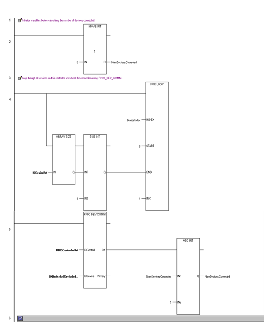
PACSystems™ RX3i Hot Standby CPU Redundancy User Manual Appendix C
GFK-2308W May 2021
Appendix C 152
Figure 47: Ladder Logic Example Part 1
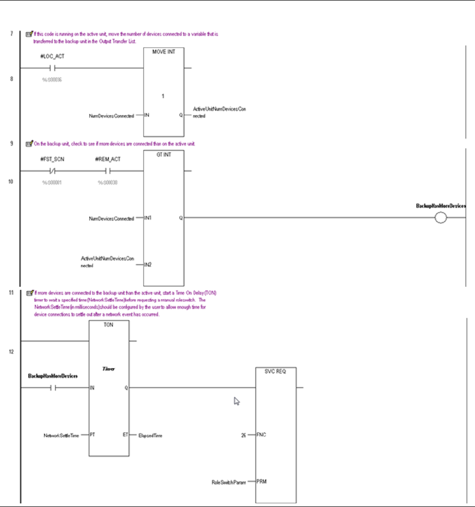
PACSystems™ RX3i Hot Standby CPU Redundancy User Manual Appendix C
GFK-2308W May 2021
Appendix C 153
Figure 48: Ladder Logic Example Part 2
PACSystems™ RX3i Hot Standby CPU Redundancy User Manual Appendix D
GFK-2308W May 2021
Appendix D 154
Appendix D Redundant I/O Wiring Details And
Programming Strategies
D 1.1 Introduction
A requirement for some high availability systems is redundant inputs and outputs (I/O).
Redundant I/O is implemented by installing two I/O modules of the required type, then
wiring the input device(s) to the redundant I/O modules. Appropriate programming may
be required to handle the redundant I/O and provide notification of discrepancies.
Emerson provides solutions for redundant controllers, but redundant I/O is not generally
provided as standard (an exception to this is Genius Modular Redundancy (GMR), but this
is now discontinued).
This document describes how redundant I/O may be implemented, including wiring
details and programming strategies.
These wiring details and programming strategies are based around systems that operate
in a duplex mode, where two devices operate simultaneously. Similar techniques may be
used in a hot-standby redundancy system where two devices operate with one device in
charge (the master) and the other is on standby in the event of a failure of the master.
D 1.2 Redundant I/O Wiring Details
Redundant I/O is implemented by installing at least two I/O modules of the required type,
then wiring the input device(s) to the redundant I/O modules. The following sections
provide wiring details for redundant I/O.
These wiring details are based around systems that operate in a duplex mode, where two
devices operate simultaneously. Similar techniques may be used in a hot-standby
redundancy system where two devices operate with one device in charge (the master) and
the other is on standby in the event of a failure of the master.
To prevent a single module failure from causing a loss of the I/O device, the use of two
separate I/O modules is recommended. These should be on separate carriers/racks to
avoid a common point of failure. Redundant power supplies could also be considered, this
may be implemented externally using appropriate power supply wiring.
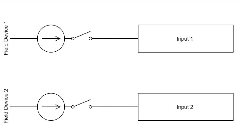
PACSystems™ RX3i Hot Standby CPU Redundancy User Manual Appendix D
GFK-2308W May 2021
Appendix D 155
D 1.3 Dual Redundant Discrete Inputs With Dual Redundant
Field Device
Where there are dual redundant field devices, each field device may be wired separately to
two inputs as shown in Figure 49.
Figure 49: Dual Redundant Discrete Inputs with Dual Redundant Field Device
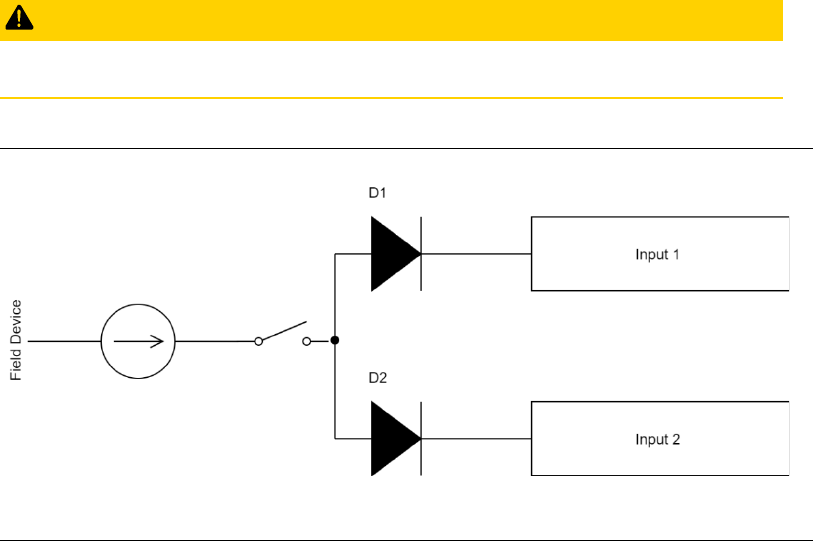
PACSystems™ RX3i Hot Standby CPU Redundancy User Manual Appendix D
GFK-2308W May 2021
Appendix D 156
D 1.4 Dual Redundant Discrete Inputs With Single Field Device
Ideally, there will be redundant field devices but in practice there is often a single field
device. In this case, the field device may be wired via diodes to two inputs as shown in
Figure 50. There is a volt drop across a diode (0.6V for silicon diodes) but this is negligible
for most industrial circuits operating at 24Vdc. In general, diodes fail open-circuit so in the
event of a failure the corresponding input will no longer operate.
CAUTION
Diodes are not suitable for AC circuits.
Figure 50: Dual Redundant Discrete Inputs with Single Field Device Wiring

PACSystems™ RX3i Hot Standby CPU Redundancy User Manual Appendix D
GFK-2308W May 2021
Appendix D 157
D 1.5 Dual Redundant Analogue Inputs With Dual Redundant
Field Device
Where there are dual redundant field devices, each field device may be wired separately to
two inputs as shown in Figure 51.
Figure 51: DUal Redndant Analog Inputs with Dual Redundant Field Device Wiring
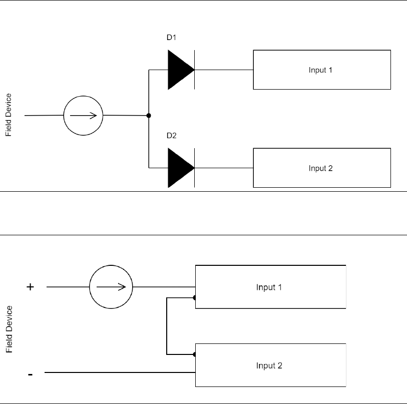
PACSystems™ RX3i Hot Standby CPU Redundancy User Manual Appendix D
GFK-2308W May 2021
Appendix D 158
D 1.6 Dual Redundant Analogue Inputs With Single Field Device
Ideally, there will be redundant field devices but in practice there is often a single field
device. In this case, where the field device outputs a voltage the field device may be wired
via diodes to two inputs as shown in Figure 51 . There is a volt drop across a diode (0.6V for
silicon diodes). Where low voltages are used, this approach may be unsuitable. Where the
field device outputs a current the field device may be wired to two inputs in series as
shown in . There is a volt drop across a diode (0.6V for silicon diodes). In general, diodes
fail open-circuit so in the event of a failure the corresponding input will no longer operate.
Figure 52: Dual Redundant Voltage Analog Input with Single Field Device Wiring
Figure 53: Dual Redundant Current Analog Inputs wit Single Device Wiring
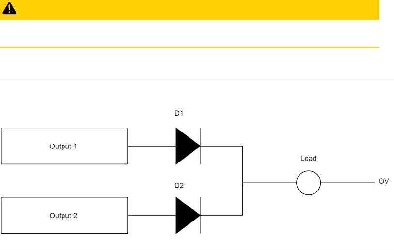
PACSystems™ RX3i Hot Standby CPU Redundancy User Manual Appendix D
GFK-2308W May 2021
Appendix D 159
D 1.7 Dual Redundant Discrete Outputs with Single Field Device
Ideally, there will be redundant field devices but in practice there is often a single field
device. In this case, the field device may be wired via diodes to two outputs as shown in
Figure 54. There is a volt drop across a diode (0.6 V for silicon diodes) but this is negligible
for most industrial circuits operating at 24 Vdc. In general, diodes fail open-circuit so in
the event of a failure the output device will be driven by the remaining working output.
Where it is critical that the output does not operate when there is a failure, input feedback
may be used.
CAUTION
Diodes are not suitable for AC circuits.
Figure 54: Dual Redundant Discrete Outputs with Single Field Device Wiring
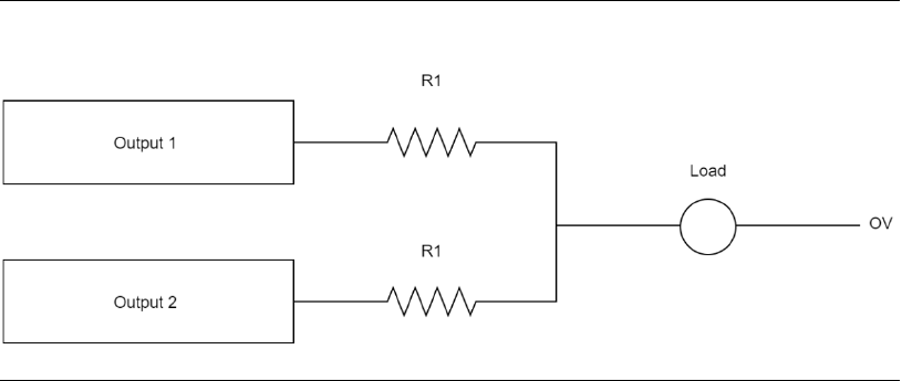
PACSystems™ RX3i Hot Standby CPU Redundancy User Manual Appendix D
GFK-2308W May 2021
Appendix D 160
D 1.8 Dual Redundant Analogue Outputs With Single Field
Device
In practice, redundant analogue outputs are rarely used.
Ideally, there will be redundant field devices but in practice there is often a single field
device. In this case, the field device may be wired via resistors to two outputs as shown in
Figure 55. There is a volt drop across each resistor, the effect of this must be calculated
based on the load and the resistor value. Where it is critical that the output does not
operate when there is a failure, input feedback may be used.
Figure 55: Dual Redundant Voltage Analog Outputs with a Single Field Device Wiring
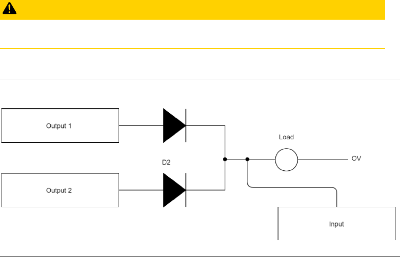
PACSystems™ RX3i Hot Standby CPU Redundancy User Manual Appendix D
GFK-2308W May 2021
Appendix D 161
D 1.9 Dual Redundant Outputs With Single Field Device And
Input Feedback
Ideally, there will be redundant field devices but in practice there is often a single field
device. In this case, the field device may be wired via diodes to two outputs as shown in
Figure 56 . There is a volt drop across a diode (0.6 V for silicon diodes) but this is negligible
for most industrial circuits operating at 24 Vdc.
In general, diodes fail open-circuit so in the event of a failure the output device will be
driven by the remaining working output. Where it is critical that the output does not
operate when there is a failure, input feedback may be used to determine if the output is
on even when not commanded to be on. Additional circuitry will be required to take
action in the event of this failure mode.
CAUTION
Diodes are not suitable for AC circuits.
Figure 56: Dual Redundant Outputs with Single Field Device and Input Feedback Wiring
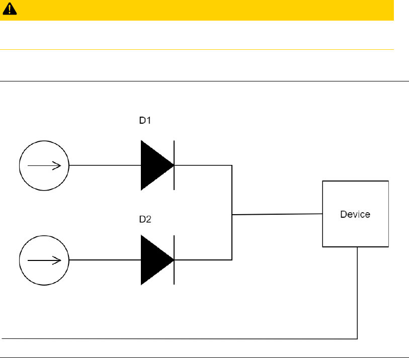
PACSystems™ RX3i Hot Standby CPU Redundancy User Manual Appendix D
GFK-2308W May 2021
Appendix D 162
D 1.10 Redundant Power Supply Wiring
Redundant power supplies may be implemented externally using power supply wiring
using diodes as shown in Figure 57. There is a volt drop across a diode (0.6 V for silicon
diodes) but this is negligible for most industrial circuits operating at 24 Vdc. This
arrangement does not protect against overvoltage; power supplies with overvoltage
detection and crowbar protection are recommended.
This arrangement could be combined with input feedback to detect a power supply
failure.
CAUTION
Diodes are not suitable for AC circuits.
Figure 57: Redundant Power Supply Wiring
D 1.11 Alternatives to Diodes
Diodes are highly reliable electronic devices with a long life and predictable failure mode.
However, they are not suitable for AC circuits. For AC circuits, or where the volt drop is
unacceptable, relays could be used. However, relays are electromagnetic devices with a
shorter life and unpredictable failure mode so are not recommended.

PACSystems™ RX3i Hot Standby CPU Redundancy User Manual Appendix D
GFK-2308W May 2021
Appendix D 163
D 1.12 Redundant I/O Programming Strategies
Appropriate programming may be required to handle the redundant I/O and provide
notification of discrepancies. The following sections provide programming strategies for
redundant I/O.
These programming strategies are based around systems that operate in a duplex mode,
where two devices operate simultaneously. Similar techniques may be used in a hot-
standby redundancy system where two devices operate with one device in charge (the
master) and the other is on standby in the event of a failure of the master.
Note that for discrepancy detection, time delays may be required to allow for
communications delays and input or output settling time.
These programming strategies may be implemented as user defined function blocks
(UDFBs) to allow simple re-use. Emerson does not generally provide such blocks due to
the large range of products and potential architectures available, however Emerson may
be contracted to write such blocks where appropriate. Please contact your Emerson agent
for further information.
D 1.13 Dual Redundant Discrete Inputs
Where there are dual redundant discrete inputs, each input may be ORed to provide an
actual input. Additional logic may be implemented to detect discrepancies.
Figure 58: Dual Redundant Discrete Inputs Programming
VOTED_INPUT = INPUT1 OR INPUT2
ERROR = INPUT1 <> INPUT2

PACSystems™ RX3i Hot Standby CPU Redundancy User Manual Appendix D
GFK-2308W May 2021
Appendix D 164
D 1.14 Dual Redundant Analogue Inputs
Where there are dual redundant analogue inputs, the inputs may be averaged to provide
an actual input. Additional logic may be implemented to detect discrepancies.
Figure 59: Dual Redundant Analog Inputs Programming
VOTED_INPUT = (INPUT1 + INPUT2) / 2
ERROR = ((((INPUT1 + INPUT2) / 2) – INPUT1) <> DEADBAND) OR
((((INPUT1 + INPUT2) / 2) – INPUT2) <> DEADBAND)
D 1.15 Dual Redundant Outputs
Where there are dual redundant outputs, both outputs may be controlled by the same
logic to generate the same result.
D 1.16 Dual Redundant Outputs With Input Feedback
Where there are dual redundant outputs, both outputs may be controlled by the same
logic to generate the same result. Additional logic may be implemented to detect
discrepancies.
Figure 60: Dual Redundant Outputs with Input Feedback Programming
ERROR = (INPUT <> OUTPUT1) OR (INPUT <> OUTPUT2)

PACSystems™ RX3i Hot Standby CPU Redundancy User Manual Appendix D
GFK-2308W May 2021
Appendix D 165
D 1.17 Glossary
Figure 61: Glossary
Term
Description
Discrepancy
Difference between what is expected and what actually
occurs or is seen
Duplex
Redundancy system where two devices (or more) operate
simultaneously. Requires voting of I/O to handle
discrepancies or communications failures
Hot-standby
Redundancy system where two devices (or more) operate,
one device is in charge (the master) and the other is on
standby in the event of a failure of the master. No voting
required since the I/O only needs to communicate with the
master.
I/O
Inputs and Outputs
Master
Main device in a hot-standby system
Standby
Backup device in a hot-standby system
UDFB
User Defined Function Block
Voting
Strategy where a “vote” must be taken on which I/O to use
where there is a discrepancy or communications failure

General Contact Information
Home link: http://www.emerson.com/industrial-automation-controls
Knowledge Base: https://www.emerson.com/industrial-automation-controls/support
Technical Support
Americas
Phone: 1-888-565-4155
1-434-214-8532 (If toll free option is unavailable)
Customer Care (Quotes/Orders/Returns): customerc[email protected]m
Technical Support: [email protected]m
Europe
Phone: +800-4444-8001
+420-225-379-328 (If toll free option is unavailable)
+39-0362-228-5555 (from Italy - if toll-free 800 option is unavailable or dialing from a
mobile telephone)
Customer Care (Quotes/Orders/Returns): customercare.emea.mas@emerson
Technical Support: support.mas.emea@emerson.com
Asia
Phone: +86-400-842-8599
+65-6955-9413 (All other Countries)
Customer Care (Quotes/Orders/Returns): customerc[email protected]m
Technical Support: support.mas.apac@emerson.com
Any escalation request should be sent to: mas.sfdcescala[email protected]
Note: If the product is purchased through an Authorized Channel Partner, please contact the seller
directly for any support.
Emerson reserves the right to modify or improve the designs or specifications of the products mentioned in
this manual at any time without notice. Emerson does not assume responsibility for the selection, use or
maintenance of any product. Responsibility for proper selection, use and maintenance of any Emerson
product remains solely with the purchaser.
© 2021 Emerson. All rights reserved.
Emerson Terms and Conditions of Sale are available upon request. The Emerson logo is a trademark and
service mark of Emerson Electric Co. All other marks are the property of their respective owners.
